Overhanging wall cap building structure system for shear wall barrel of high-rise building

A technology for high-rise buildings and building structures, which is applied in the direction of building structures and buildings, can solve problems such as limited stiffness and bearing capacity, difficulty in making up for stiffness defects, and increasing the cost of building structures, so as to improve stress, increase stiffness, and increase resistance. The effect of shear ability

Active Publication Date: 2013-12-04
ARCHITECTURAL DESIGN RES INST OF GUANGDONG PROVINCE
View PDF3 Cites 6 Cited by
  • Summary
  • Abstract
  • Description
  • Claims
  • Application Information

AI Technical Summary

Problems solved by technology

Since flat beams have lower rigidity compared with ordinary beams of the same cross-sectional area (beams whose cross-sectional height ≥ width), if other technical measures are taken to compensate for their rigidity, such as adding steel to the beam or making it into a steel beam, it is It can improve the stiffness and bearing capacity of flat beams to a certain extent, but this treatment method is limited to improve the stiffness and bearing capacity of beams, and often still cannot meet the above-mentioned requirements of large beam spans in high-rise buildings. The limitation of storey height and the height requirements of rational use of space lead to the contradiction between the limitation of beam section height and the building structure system, especially the beam rigidity requirements, that is, it is often difficult to make up for the impact caused by the use of flat beams in high-rise buildings on the overall building structure system. Due to the rigidity defects that come, and because the cost of steel is increasing day by day, it will also significantly increase the cost of building structures, which is not conducive to popularization and application

Method used


Image

  • Overhanging wall cap building structure system for shear wall barrel of high-rise building
  • Overhanging wall cap building structure system for shear wall barrel of high-rise building
  • Overhanging wall cap building structure system for shear wall barrel of high-rise building

Examples


Embodiment Construction

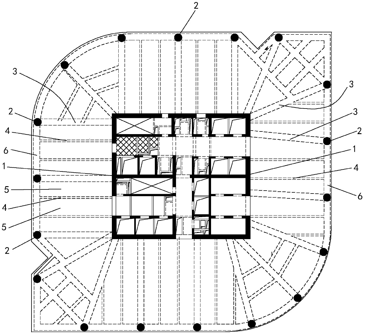
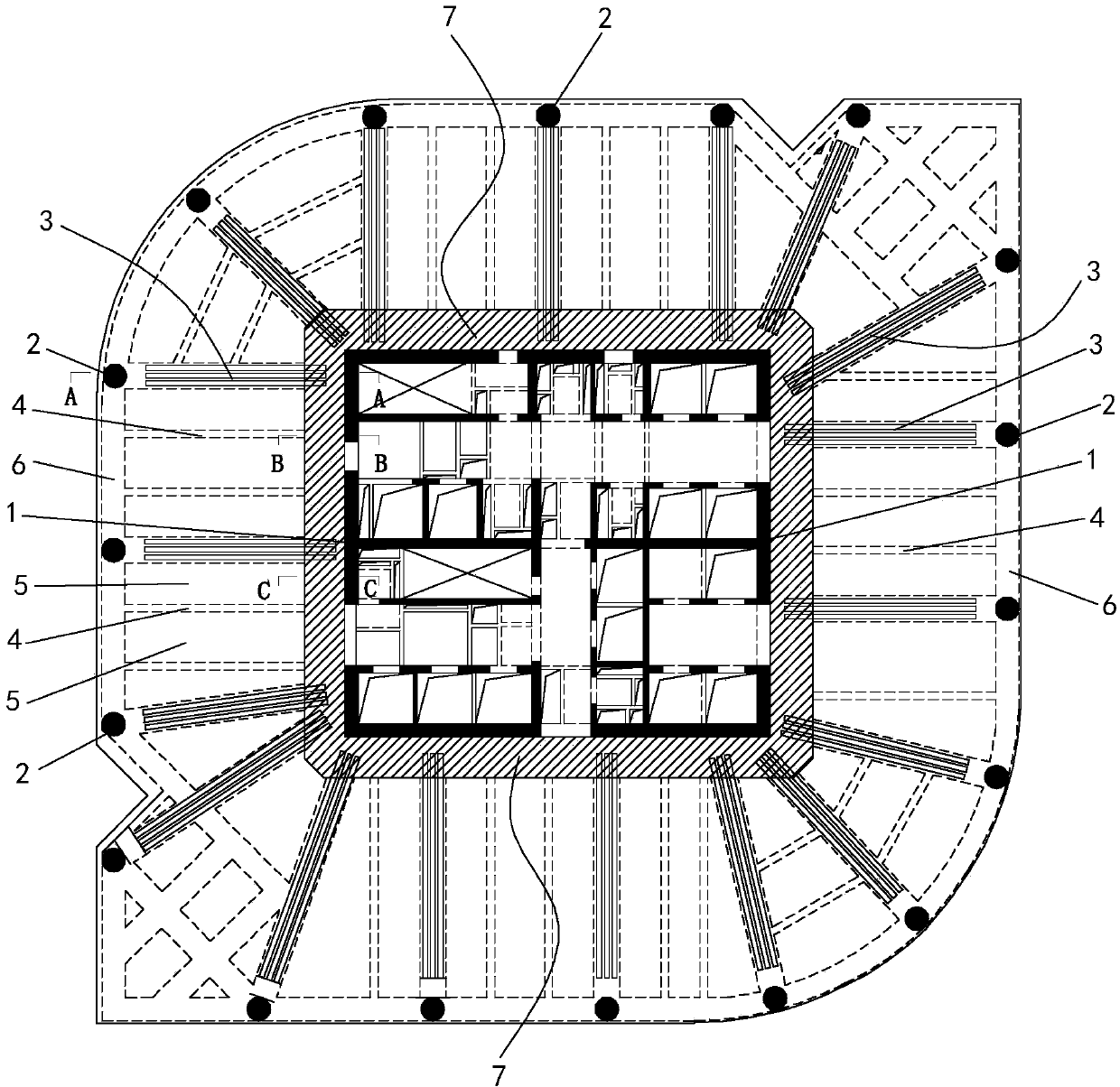
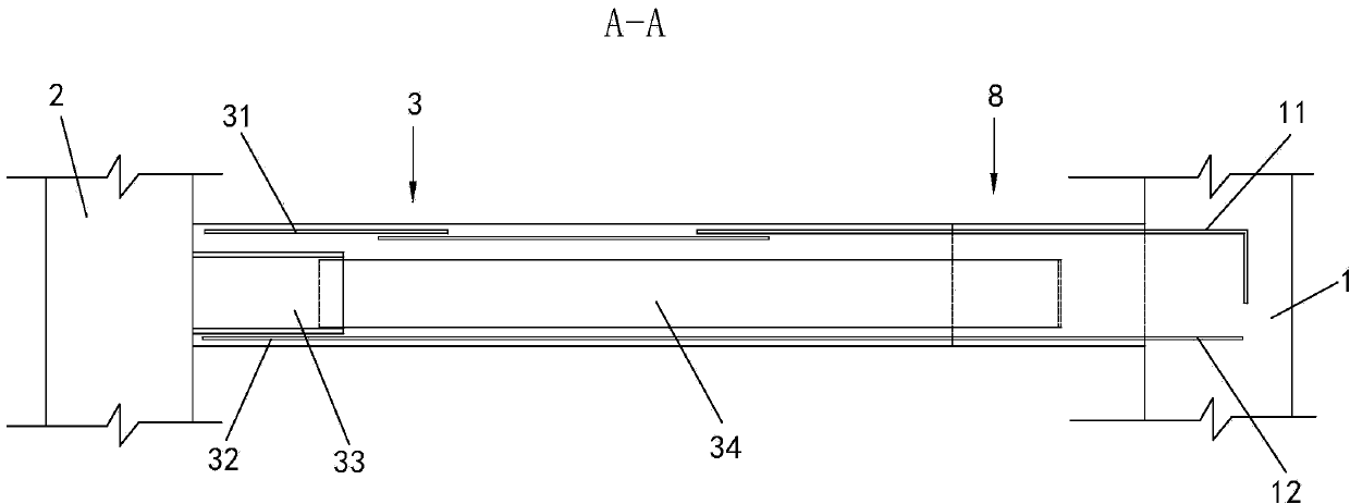
[0038] Such as Figure 2 to Figure 7 Shown is a high-rise building shear wall cylinder external extension wall cap building structure system, which is composed of a shear wall cylinder 1, a frame beam 3, a secondary beam 4, a frame column 2, an outer ring frame beam 6 and a floor slab 5. The force wall cylinder 1 is arranged vertically and is located at the center of the high-rise building. The frame column 2 is a reinforced concrete column arranged vertically. The frame column 2 is located on the periphery of the shear wall cylinder 1. Between adjacent frame columns 2 The outer ring frame beam 6 is built, and the frame beam 3 and the secondary beam 4 are horizontally erected beams, wherein the two ends of the frame beam 3 are respectively erected on the frame column 2 and the shear wall cylinder 1, and the secondary beam 4 is respectively erected On the frame beam 6 of the outer ring and the shear wall cylinder 1, the frame beam 3 and the secondary beam 4 are distributed in a...


PUM


Abstract

The invention discloses an overhanging wall cap building structure system for a shear wall barrel of a high-rise building. The building structure system consists of the shear wall barrel, frame beams, secondary beams, frame columns, outer-circle frame beams, floor slabs and wall caps, wherein the shear wall barrel is positioned at the central position of the high-rise building; the frame columns are positioned on the periphery of the shear wall barrel; the two ends of the frame beams are erected on the frame columns and the shear wall barrel respectively; the secondary beams are erected on the outer-circle frame beams and the shear wall barrel respectively; each wall cap is a closed annular cap edge-shaped structural body which is arranged on the outer wall of the corresponding layer of the shear wall barrel in an enclosing way and outwards and horizontally extends along the radial direction of the shear wall barrel; inner-end reinforcement bars of the wall caps are arranged in the shear wall barrel, and are connected and cast integrally with reinforcement bars of the shear wall barrel; the outer ends of the wall caps are shaped like cantilevers, and are fixedly connected with the corresponding frame beams or the corresponding secondary beams or the corresponding floor slabs. According to the building structure system, under the conditions of large beam span and limited sectional heights, the rigidity and the bearing capacity of the beams can be effectively improved, and the rigidity of a shear wall can be improved.

Description

technical field [0001] The invention relates to a high-rise building structure, in particular to a high-rise building shear wall cylinder external extension wall cap building structure system. Background technique [0002] The shear wall cylinder is widely used in high-rise buildings because of its good shear resistance. The existing high-rise building shear wall cylinder structure system is as follows: figure 1 As shown, including shear wall cylinder 1, frame beam 3, secondary beam 4 and frame column 2, shear wall cylinder 1 is vertically arranged at the center of a high-rise building, and frame column 2 is located in the shear wall cylinder 1, the frame column 2 is a plurality of vertically arranged steel tube concrete columns, and the outer ring frame beam 6 is built between the adjacent frame columns 2, and the frame beam 3 and the secondary beam 4 are multiple beams erected horizontally. Among them, the two ends of the frame beam 3 are respectively erected on the frame...

Claims


Application Information

Patent Timeline
Patent Type & Authority Applications(China)
IPC IPC(8): E04B1/04E04B1/30E04B1/41
Inventor 陈星王仕琪欧妍君林扑强赖鸿立林景华吴桂广苏恒强温文浩黄燕鹏连丽凌张小良陈航倪炜麟邱丽琴
Owner ARCHITECTURAL DESIGN RES INST OF GUANGDONG PROVINCE
Why Eureka
Try Eureka