
Rotor type external combustion engine air cylinder and rotor type external combustion engine

An external combustion engine, rotor type technology, applied in the direction of machine/engine, hot gas variable capacity engine device, mechanical equipment, etc., to achieve the effect of improving work efficiency, high power output, and improving the ability of expansion to do work

Inactive Publication Date: 2013-12-04
JIANGSU UNIV
View PDF9 Cites 4 Cited by
  • Summary
  • Abstract
  • Description
  • Claims
  • Application Information

AI Technical Summary

Problems solved by technology

[0009] The present invention provides a Rotor-type external-combustion engine, which combines the advantages of existing external-combustion engines and can meet the requirements of high efficiency, high power output and wide-range continuously variable speed at the same time

Method used


Image

  • Rotor type external combustion engine air cylinder and rotor type external combustion engine
  • Rotor type external combustion engine air cylinder and rotor type external combustion engine
  • Rotor type external combustion engine air cylinder and rotor type external combustion engine

Examples


Embodiment 1

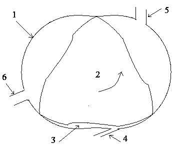
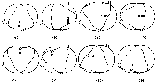
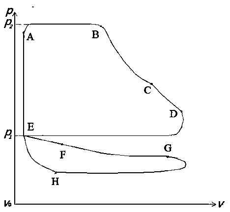
[0034] Such as figure 1 , figure 2 as well as Figure 5 As shown, a cylinder of a rotor-type external combustion engine includes a cylinder block 1, on which an intake pipe 4 and an exhaust pipe are arranged, and the inside of the cylinder block 1 also includes a triangular rotor 2; the triangular rotor 2 is in contact with the inner wall of the cylinder; The rotor 2 and the cylinder 1 form a working room 3, which is a dynamic airtight space; there are two exhaust pipes, including the primary exhaust pipe 5 and the secondary exhaust pipe 6; the inlet pressure of the intake pipe 4 is 10MPa ; The diameter of the air inlet pipe 4 is 40mm. In addition, the nozzle of the intake pipe 4 is located at the position where the short axis of the cylinder block 1 rotates 20° counterclockwise, and the angle formed by the center line of the intake pipe 4 and the long axis of the cylinder block is 25°. The included angle formed by the 5 nozzles of the primary exhaust pipe and the short a...

Embodiment 2

[0037] Same as embodiment 1, the difference is that the air inlet pressure is 25MPa, the diameter is 50mm, and the mouth of the air intake pipe 4 is located directly below the cylinder block, that is, at the short axis, and the clamp formed by the center line of the air intake pipe 4 and the long axis of the cylinder body Angle is 10. The angle formed by the 5 nozzles of the primary exhaust pipe and the short axis of the cylinder is 30; the angle formed by the 6 nozzles of the secondary exhaust pipe and the long axis of the cylinder is also 30.

Embodiment 3

[0039] Same as embodiment 1, the difference is that the air inlet pressure is 50MPa, the diameter is 60mm and the mouth of the air inlet pipe 4 is located at the position where the short axis of the cylinder rotates 45 degrees counterclockwise, and the centerline of the air inlet pipe 4 and the long axis of the cylinder form the The included angle is 40°. The angle formed by the 5 nozzles of the primary exhaust pipe and the short axis of the cylinder body is 45°; the angle formed by the 6 nozzles of the secondary exhaust pipe and the long axis of the cylinder body is also 45°.


PUM


Abstract

The invention discloses a novel external combustion engine based on the pneumatic principle, and belongs to the field of external combustion engines of a power mechanical system. An external combustion engine air cylinder comprises a cylinder body, wherein a gas inlet pipe and gas exhaust pipes are arranged on the cylinder body, and the interior of the cylinder body further comprises a triangular rotor. The triangular rotor makes contact with the inner wall of the cylinder body, a working chamber is formed by the triangular rotor and the cylinder body, and the working chamber is a dynamic sealing space. The number of the gas exhaust pipes is two, and the gas exhaust pipes comprise the primary gas exhaust pipe and the secondary gas exhaust pipe. According to the rotor type external combustion engine, the advantages of an existing external combustion engine are integrated, and meanwhile the requirements for high-power output and large-range electrodeless speed change are met.

Description

technical field [0001] The invention belongs to the field of external combustion engines of power machinery systems, and is a novel external combustion engine invented based on the principle of aerodynamics. Background technique [0002] The external combustion engine is also called the external combustion engine. Although it and the internal combustion engine use the internal energy of the fuel to convert it into mechanical energy, their working methods are quite different. Among them, the internal combustion engine burns the mixture of fuel and air in the cylinder to directly convert the generated heat energy into mechanical energy, while the external combustion engine directly passes the high-temperature and high-pressure combustion products obtained by burning in the external combustion chamber into the external combustion engine. The combustion product expands and converts its kinetic energy into mechanical energy at the same time, or uses the combustion product to heat...

Claims


Application Information

Patent Timeline
Patent Type & Authority Applications(China)
IPC IPC(8): F02G3/00
Inventor 范宝伟潘剑锋潘振华唐爱坤薛宏
Owner JIANGSU UNIV
Learn More