Super-resolution confocal microimaging method and device based on column polarization vortex beam

A confocal microscopic imaging and vortex beam technology, which is applied in the field of super-resolution confocal microscopic imaging, can solve the problems of limited ability to improve resolution, insignificant effect, and inability to infinitely reduce the wavelength of incident light.

Active Publication Date: 2013-12-04
BEIJING INFORMATION SCI & TECH UNIV
View PDF2 Cites 38 Cited by
  • Summary
  • Abstract
  • Description
  • Claims
  • Application Information

AI Technical Summary

Problems solved by technology

However, the ability of this adjustment to improve the resolution is still very limited, because the wavelength of the incident light cannot be reduced infinitely, and the numerical aperture of the imaging objective lens is also limited.
Research in recent years has shown that the measurement resolution of the confocal system can be further improved by adopting pupil filtering, 4Pi illumination and interference technology, but the improvement effect is not very obvious, so it is necessary to find a new technological breakthrough

Method used


Image

  • Super-resolution confocal microimaging method and device based on column polarization vortex beam
  • Super-resolution confocal microimaging method and device based on column polarization vortex beam
  • Super-resolution confocal microimaging method and device based on column polarization vortex beam

Examples


Embodiment Construction

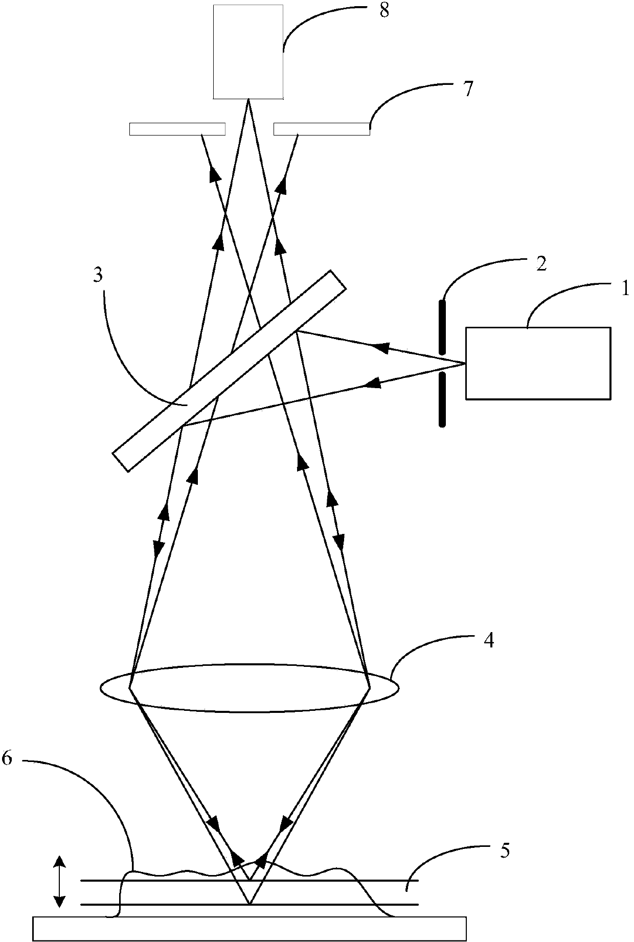
[0019] The present invention will be described in detail below in conjunction with the accompanying drawings and embodiments, but the present invention is not limited thereto.

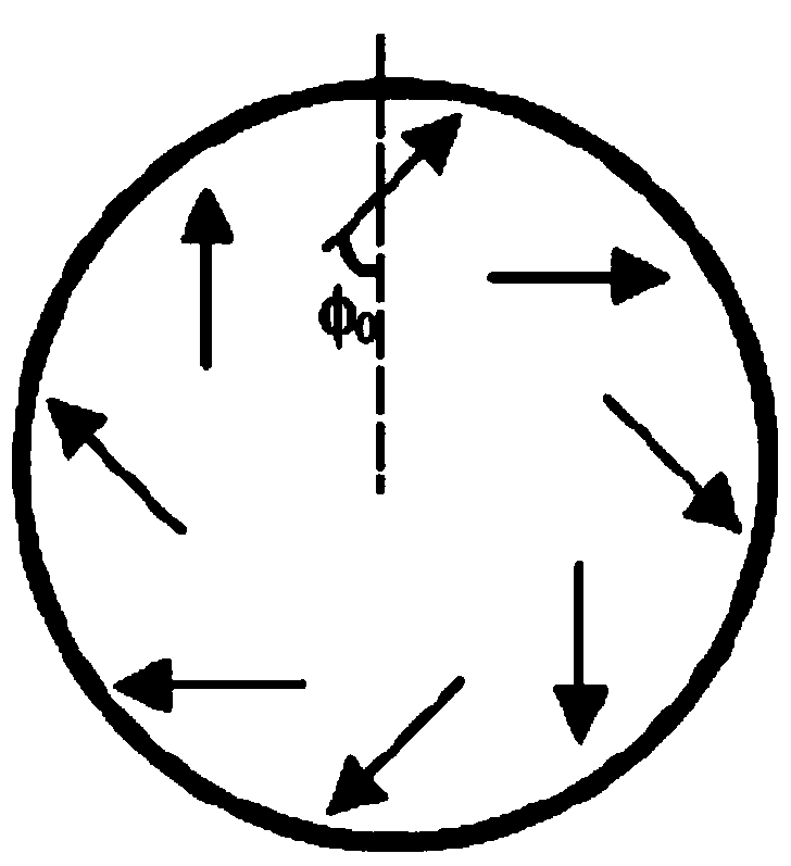
[0020] Figure 2(a)-Figure 2(d) is the polarization distribution characteristics on the cross-section of the cylindrical vector beam, where Figure 2(a) is the initial azimuth angle φ 0 The cylindrical vector beam of Fig. 2 (b) is a radially polarized beam, Fig. 2 (c) is a tangentially polarized beam, and Fig. 2 (d) is a method for obtaining a vortex beam using a vortex phase plate.

[0021] As shown in Figure 2(a), a cylindrical vector beam is a kind of polarized beam whose polarization state on the beam cross section has cylindrical symmetry characteristics with respect to the beam propagation axis. In the local part of the beam cross section, the polarization state of the beam is linearly polarized , but its polarization direction varies spatially. When the initial polarization azimuth angle φ0 of th...


PUM

PropertyMeasurementUnit
refractive indexaaaaaaaaaa

Abstract

The invention provides a super-resolution confocal microimaging device based on a column polarization vortex beam. The super-resolution confocal microimaging device comprises a pinhole filter, a collimating lens, a polarization and phase transformation system, a pupil filter, an optical filter, a detector and a three-dimensional translational platform, wherein a beam emitted from a laser passes the pinhole filter to obtain a Gauss basic mode beam, the collimating lens collimates the Gauss basic mode beam into the parallel beam, the polarization and phase transformation system allows the parallel beam to pass and obtain the column polarization vortex beam with preset polarization and phase distribution, the pupil filter allows the column polarization vortex beam to pass and to be reflected through a beam splitter and focused on a to-be-detected sample through a collecting lens, light signals reflected from the sample pass the collecting lens and the beam splitter to be incident on the optical filter, and the optical filter only allows a fluorescence signal of the light signals to be transmitted, the fluorescence signal is focused on a detecting pinhole through the collecting lens and is detected and converted, through the detector, into an electrical signal to be output, the sample is placed on the three-dimensional translational platform, detection of the sample at different positions can be realized by moving the three-dimensional translational platform, and accordingly three-dimensional scanning imaging of the sample can be realized.

Description

technical field [0001] The invention relates to confocal microscopic imaging technology, in particular to a method and device for super-resolution confocal microscopic imaging using cylindrically polarized vortex beams. Background technique [0002] The development of modern biology and material science has put forward higher and higher resolution requirements for the study of microstructure, hoping to reveal the physical essence of life processes and material properties from the molecular level. However, limited by the optical diffraction limit, the horizontal resolution of ordinary optical microscopes can only reach 200nm, and the vertical resolution is about 500nm, which is powerless for the study of subcellular and molecular structures. Although electron microscopy (Electron Microscopy), atomic force microscopy (Atom Force Microscopy), near-field scanning optical microscopy (Near-field Scanning Optical Microscope, NSOM) and other techniques can obtain high resolution, du...

Claims


Application Information

Patent Timeline
Patent Type & Authority Applications(China)
IPC IPC(8): G02B21/36G02B27/09G02B27/28G01N21/64
Inventor 周哲海祝连庆娄小平吴思进刘谦哲孟晓辰潘志康
Owner BEIJING INFORMATION SCI & TECH UNIV
Why Eureka
Try Eureka