Optimization method for photoresist layer of guide mode resonance optical filter

A photoresist layer, guided mode resonance technology, applied in the direction of filters, microlithography exposure equipment, photolithography process exposure devices, etc., can solve the problem of no filter, etc., and achieve the effect of simple operation

Inactive Publication Date: 2013-12-04
UNIV OF SHANGHAI FOR SCI & TECH
View PDF5 Cites 13 Cited by
  • Summary
  • Abstract
  • Description
  • Claims
  • Application Information

AI Technical Summary

Problems solved by technology

In terms of related prior patent documents, such as the Chinese invention patent case (publication number CN201556006), it describes the structure of a tunable guided mode resonant filter, and the middle

Method used


Image

  • Optimization method for photoresist layer of guide mode resonance optical filter
  • Optimization method for photoresist layer of guide mode resonance optical filter

Examples


specific Embodiment approach

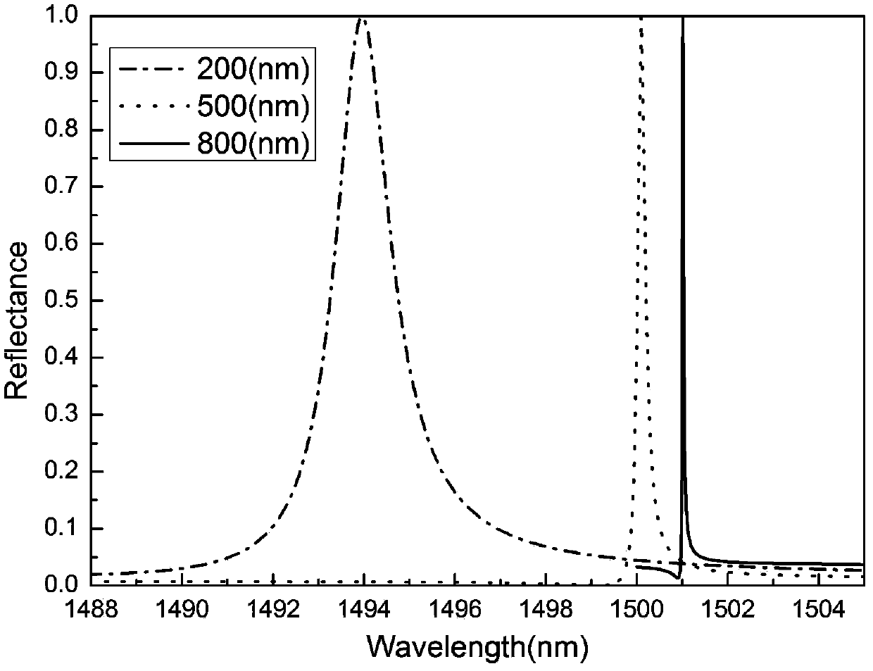
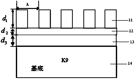
[0016] figure 1 It is a structural diagram of a guided mode resonant filter in an embodiment of the present invention; figure 2 It is the reflection spectrum diagram of the guided mode resonant filter in the embodiment of the present invention.

[0017] Such as figure 1 , 2 As shown, the structure of the filter used in the present invention includes: a substrate 14 , a grating layer 11 , an unsensitized photoresist layer 12 and a waveguide layer 13 . Thickness d of grating layer 11 1 , the thickness d of the unsensitized photoresist layer 12 2 and the thickness d of the waveguide layer 13 3 .

[0018] Steps for making a guided mode resonant filter.

[0019] Step 1: First, deposit a layer of titanium oxide film with high refractive index on the cleaned K9 glass substrate 11 by thermal evaporation.

[0020] Step 2: The transmission spectrum of the titanium oxide layer is calculated by Macleod software to obtain the thickness and refractive index of the actual film. Acco...


PUM

PropertyMeasurementUnit
Thicknessaaaaaaaaaa
Thicknessaaaaaaaaaa
Thicknessaaaaaaaaaa

Abstract

The invention mainly provides the influence of thickness of photoresist on an optical filter and an optimization method for the photoresist. The method is characterized in that diffraction grating manufacturing is performed above a waveguide layer; in exposure and development process of the photoresist, the groove depth of the grating manufactured by a final holographic method is not the practical thickness of uniform glue as being affected by the exposure time and development time, so that a layer of non-sensitive photoresist layer is also arranged on a guide mode layer and a diffraction grating layer, which directly affects the width and peak value position of the practically manufactured optical filter. The method realizes the modulating function of unsuccessfully exposed and developed photoresist on the reflection of the optical filter, not only has guiding function for the thickness maximum of the uniform glue in the practical preparation process, but also can optimize the thickness of the undeveloped photoresist to adjust the process parameters of other later period optical filter according to the results. The method is convenient to implement and can be used for the field of optical filter manufacturing and biological sensing.

Description

technical field [0001] The invention relates to a method for optimizing a photoresist layer of a guided-mode resonant filter, and belongs to the field of guided-mode resonant filters. Background technique [0002] The guided mode resonance effect is an anomalous optical phenomenon discovered by Wood in 1909, which refers to the sudden change of the diffraction spectrum caused by the coupling between the diffracted wave and the leaky mode supported by the grating structure. Due to its unique spectral line characteristics, the subwavelength grating structure is expected to replace multilayer films to make filters and mirrors. The guided mode resonance diffraction characteristics in weakly modulated subwavelength gratings can be better explained and designed by the equivalent medium theory and the dispersion characteristics of the leaky mode, so it is used to replace the traditional multilayer dielectric film to make narrow-band high reflection filters It has shown great appli...

Claims


Application Information

Patent Timeline
IPC IPC(8): G03F7/20G02B5/20
Inventor 王振云王琦唐庆勇张大伟黄元申洪瑞金倪争技盛斌陶春先
Owner UNIV OF SHANGHAI FOR SCI & TECH
Why Eureka
Try Eureka