
Matrix pulse signal generation circuit and generation method

A technology for generating circuits and pulse signals, applied in the direction of pulse generation, electric pulse generation, pulse technology, etc., can solve the problems of small pulse width adjustment range, difficulty in nanosecond pulse width, incompatibility with digital CMOS technology, etc., to reduce lead-out Effects of number, increasing number, increasing fitness

Active Publication Date: 2013-12-04
NO 771 INST OF NO 9 RES INST CHINA AEROSPACE SCI & TECH
View PDF6 Cites 10 Cited by
  • Summary
  • Abstract
  • Description
  • Claims
  • Application Information

AI Technical Summary

Problems solved by technology

[0004] The purpose of the present invention is to provide a matrix pulse signal generation circuit and generation method to solve the problem that the existing generation circuit cannot be compatible with the digital CMOS process, the pulse width adjustment range is small, it is difficult to realize the nanosecond pulse width, and an external frequency input is required.

Method used


Image

  • Matrix pulse signal generation circuit and generation method
  • Matrix pulse signal generation circuit and generation method
  • Matrix pulse signal generation circuit and generation method

Examples


Embodiment Construction

[0032] The present invention will be further described in detail below in conjunction with specific embodiments, which are explanations of the present invention rather than limitations.

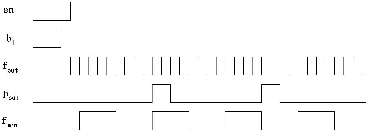
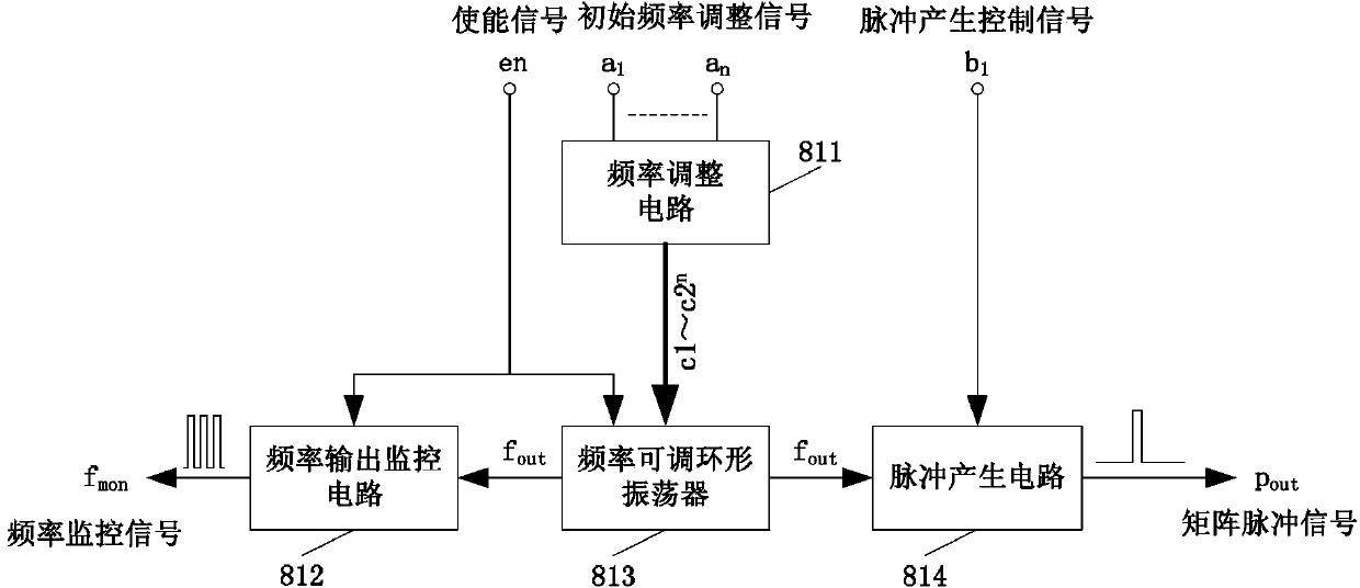
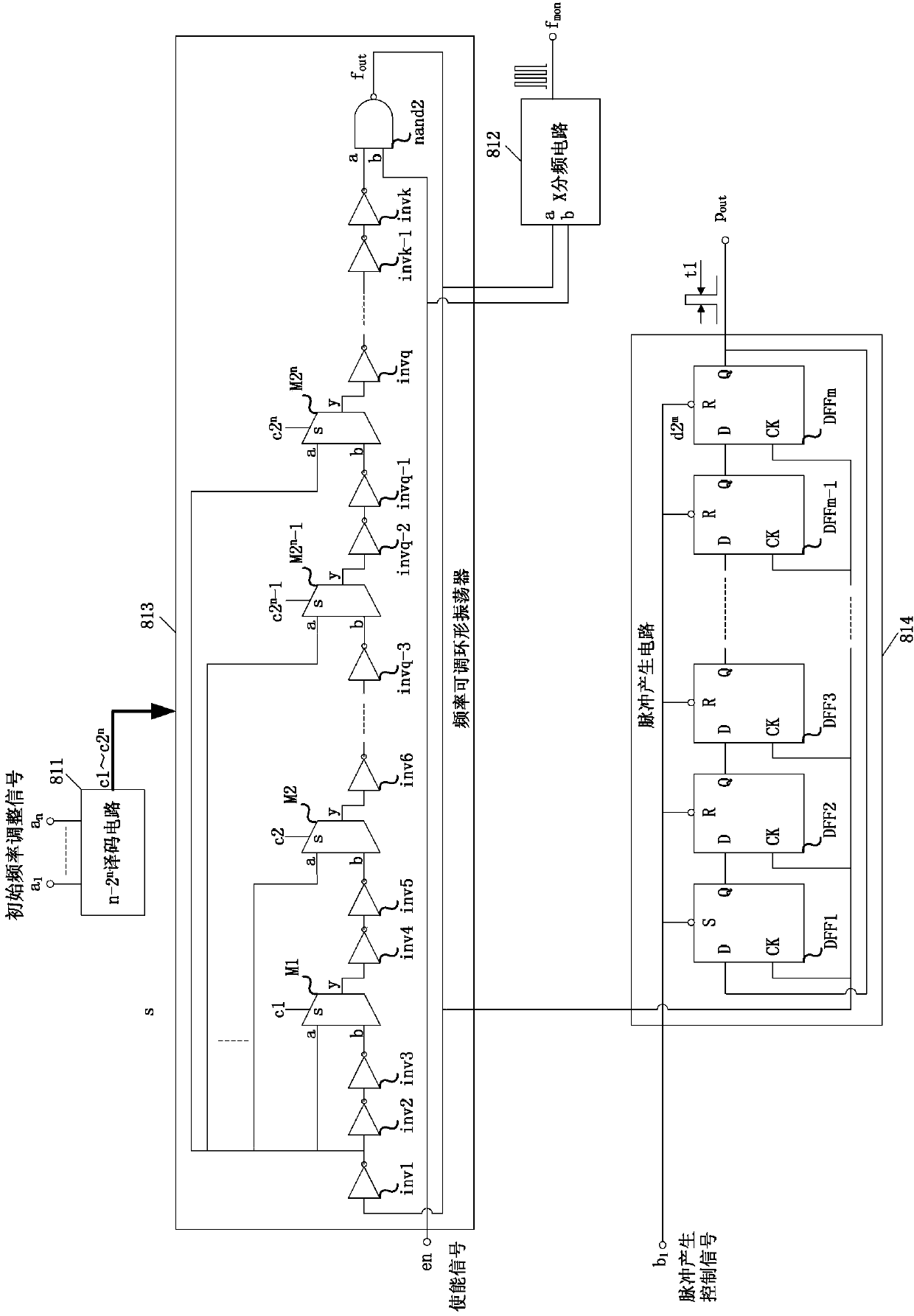
[0033] see figure 2 , a matrix pulse signal generating circuit of the present invention, which includes a frequency adjustable ring oscillator 813 and a pulse generating circuit 814; the input end of the frequency adjustable ring oscillator 813 is connected to the enable signal en, and is respectively connected to the frequency adjustment signal c1 ~cj are connected; the output terminal of the frequency adjustable ring oscillator 813 outputs a periodic output frequency signal f out , and is connected with the input end of the pulse generation circuit 814; the input end of the pulse generation circuit 814 is also connected with the pulse generation control signal b 1 connected, the output terminal of the pulse generating circuit 814 outputs a rectangular pulse signal P out ; Wherein, in thi...


PUM


Abstract

The invention discloses a matrix pulse signal generation circuit. The matrix pulse signal generation circuit comprises a frequency-adjustable annular oscillator and a pulse generation circuit, wherein the input end of the frequency-adjustable annular oscillator is connected to an enable signal and is connected to frequency adjusting signals c1-cj respectively while the output end outputs a periodic output frequency signal and is connected to an input end of the pulse generation circuit; the input end of the pulse generation circuit is also connected with a pulse generation control signal while the output end outputs a matrix pulse signal. A matrix pulse signal generation method comprises the following steps: A, setting the frequency adjusting signals c1-cj and outputting the frequency adjusting signals to the input end of the frequency-adjustable annular oscillator; B, setting the pulse generation control signal to carry out setting and resetting operations for the pulse generation circuit, and setting the pulse generation control signal at a high electric level after the setting and resetting operations are finished; C, setting an allowable enable signal for the frequency-adjustable annular oscillator to enable the frequency-adjustable annular oscillator to oscillate so as to generate and output a frequency signal, outputting the frequency signal to the pulse generation circuit, and then generating the rectangular pulse signal.

Description

technical field [0001] The invention relates to the field of semiconductor integrated circuits, in particular to a matrix pulse signal generating circuit and a generating method. Background technique [0002] A pulse signal refers to a voltage or current signal with a short duration and a specific change in width and amplitude. Common pulse signals include rectangles, zigzags, bells, and digital code sequences. The pulse signal generation circuit is widely used in switch control, digital circuit dynamic characteristic test and other fields. [0003] There are many types of pulse signal generators with different performances, but most pulse signal generators are designed with analog circuits or built with existing circuit components. This kind of pulse signal generation circuit structure cannot be compared with the current mainstream digital CMOS The integrated circuit manufacturing process is compatible, that is, it cannot be integrated into the digital integrated circuit d...

Claims


Application Information

Patent Timeline
Patent Type & Authority Applications(China)
IPC IPC(8): H03K3/017
Inventor 李海松杨博蒋轶虎唐威吴龙胜
Owner NO 771 INST OF NO 9 RES INST CHINA AEROSPACE SCI & TECH
Learn More