
Electrochromic devices with anti-iridescence coatings

An electrochromic and coating technology, applied in the direction of coating, layered products, glass/slag layered products, etc., can solve the problem of color generation and achieve the effect of high incident angle

Active Publication Date: 2016-10-12
SAGE ELECTROCHROMICS
View PDF14 Cites 0 Cited by
  • Summary
  • Abstract
  • Description
  • Claims
  • Application Information

AI Technical Summary

Problems solved by technology

[0005] However, these devices often have the disadvantage of causing coloration when reflected outwardly

Method used


Image

  • Electrochromic devices with anti-iridescence coatings
  • Electrochromic devices with anti-iridescence coatings
  • Electrochromic devices with anti-iridescence coatings

Examples


Embodiment

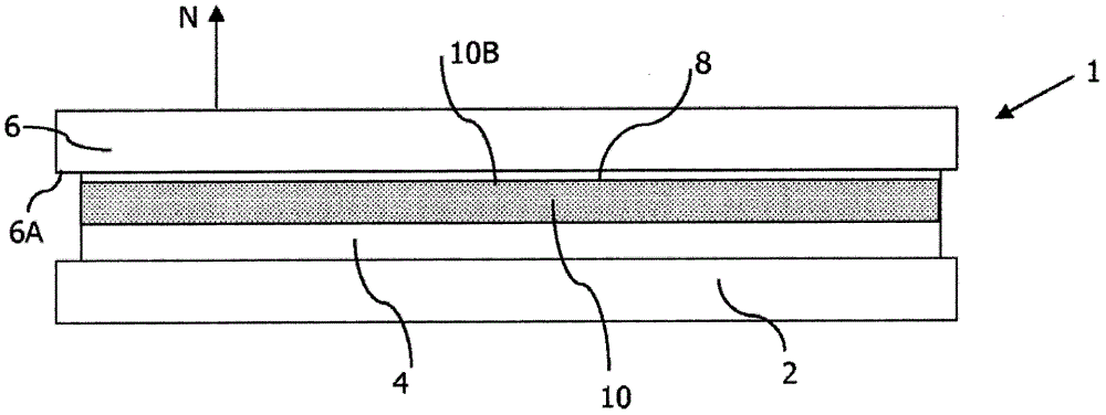
[0114] Substrate 2 is a 6 mm thick sheet of soda-lime-silicate glass.

[0115] Functional system 4 is a solid-state electrochromic system that is deposited directly on substrate 2 and consists of the following stack, starting from substrate 2:

[0116] 500nm thick ITO layer, which forms the first electrode coating / 55nm thick iridium oxide layer, which forms the first electrochromic layer / 150nm thick tungsten oxide and 300nm thick tantalum oxide layer, which forms the electrolyte / 400nm thick doped h + Tungsten oxide, which forms the second electrochromic layer / 100nm thick ITO layer, which forms the second electrode coating.

[0117] The laminate interlayer is in contact with the functional system 4 . The laminated interlayer consisted of 0.76 thick polyurethane boards.

[0118] Reflection control coating 8 is 70nm thick Si 3 N 4 layer.

[0119] The reflection control paint 8 is deposited directly on the counter substrate 6 .

[0120] The laminated interlayer 10 i...


PUM

PropertyMeasurementUnit
thicknessaaaaaaaaaa
thicknessaaaaaaaaaa
thicknessaaaaaaaaaa

Abstract

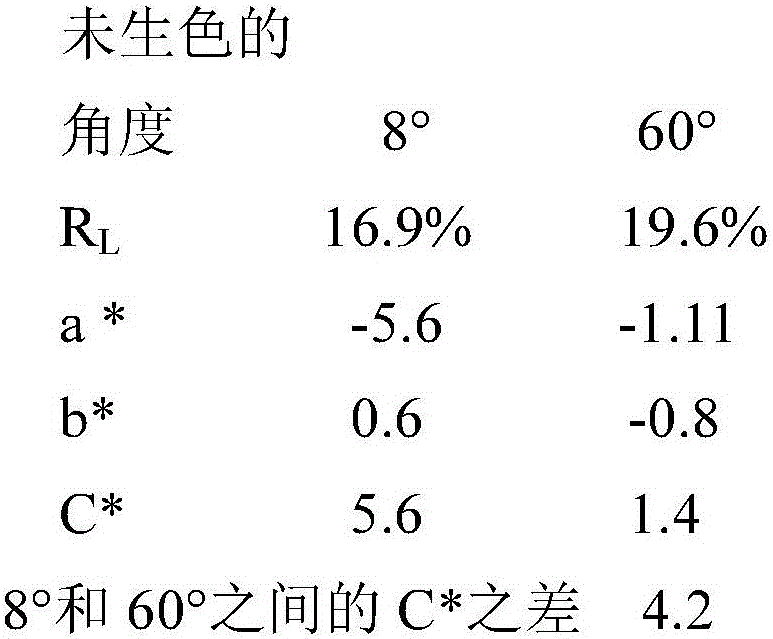
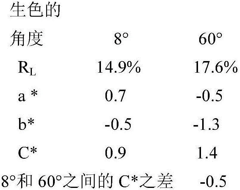
The invention relates to a device (1) of the electrochromic type comprising successively a substrate (2), a reflection control coating (8), a laminating interlayer (10), a functional system (4) of the electrochromic type and a substrate (2). This particular arrangement of the laminating interlayer between the reflection control coating and the functional system and the choice of the refractive index and thickness of the reflection control coating are such that the saturation values of C* in the colorimetric system (L*, a*, b*) of the device in reflection are less than or equal to 10 for angles of incidence of 60° and 8° relative to the normal (N) to the outer face (6B) of the counter-substrate and that the absolute value of the difference between the value of C* at an angle of incidence of 8° and the value of C* at an angle of incidence of 60° is less than or equal to 6.

Description

technical field [0001] The invention relates to the field of electrochemical devices with electrically controllable optical and / or energetic properties. Background technique [0002] The present invention relates to devices in which certain properties, especially transmission, absorption, reflection, at certain wavelengths of electromagnetic radiation, especially in the visible and / or infrared, or light scattering, can be changed under the effect of a suitable supply of electricity. Transmission changes typically occur in the optical region (infrared, visible, ultraviolet) and / or other regions of electromagnetic radiation, so that the device has variable optical and / or energy properties, and the optical region is not necessarily the only region involved. [0003] With regard to heat, glass panes whose transmission / absorption can be varied over at least part of the solar spectrum allow for controlled thermal radiation when they are installed as exterior glazing of buildings o...

Claims


Application Information

Patent Timeline
Patent Type & Authority Patents(China)
IPC IPC(8): G02F1/157B32B17/10C03C17/34
CPCB32B17/10036B32B17/10211B32B17/10513B32B17/1077C03C17/225C03C17/23C03C17/3417G02F1/157G02F2201/38
Inventor O·塞勒斯I·里普伯格P·勒图卡特J·奥利亚尔
Owner SAGE ELECTROCHROMICS
Learn More