Grain drying technology

A grain drying and grain technology, applied in drying, drying machines, food processing, etc., can solve the problems of fuel air pollution, high cost of use, and increased burden on farmers, and achieve good social benefits, cost savings, and Outstanding effect of energy saving effect

Active Publication Date: 2013-12-11
浙江天洲制冷机电有限公司
View PDF2 Cites 7 Cited by
  • Summary
  • Abstract
  • Description
  • Claims
  • Application Information

AI Technical Summary

Problems solved by technology

"Fuel oil-air supply" and "wood burning-air supply" units are all mineral and biological fuels, and the high cost of use will inevitably increase the burden on farmers in our country
Furthermore, the incomplete combustion of fuel will cause the aggravation of air pollution and the loss of energy.

Method used


Image

  • Grain drying technology
  • Grain drying technology
  • Grain drying technology

Examples


Embodiment Construction

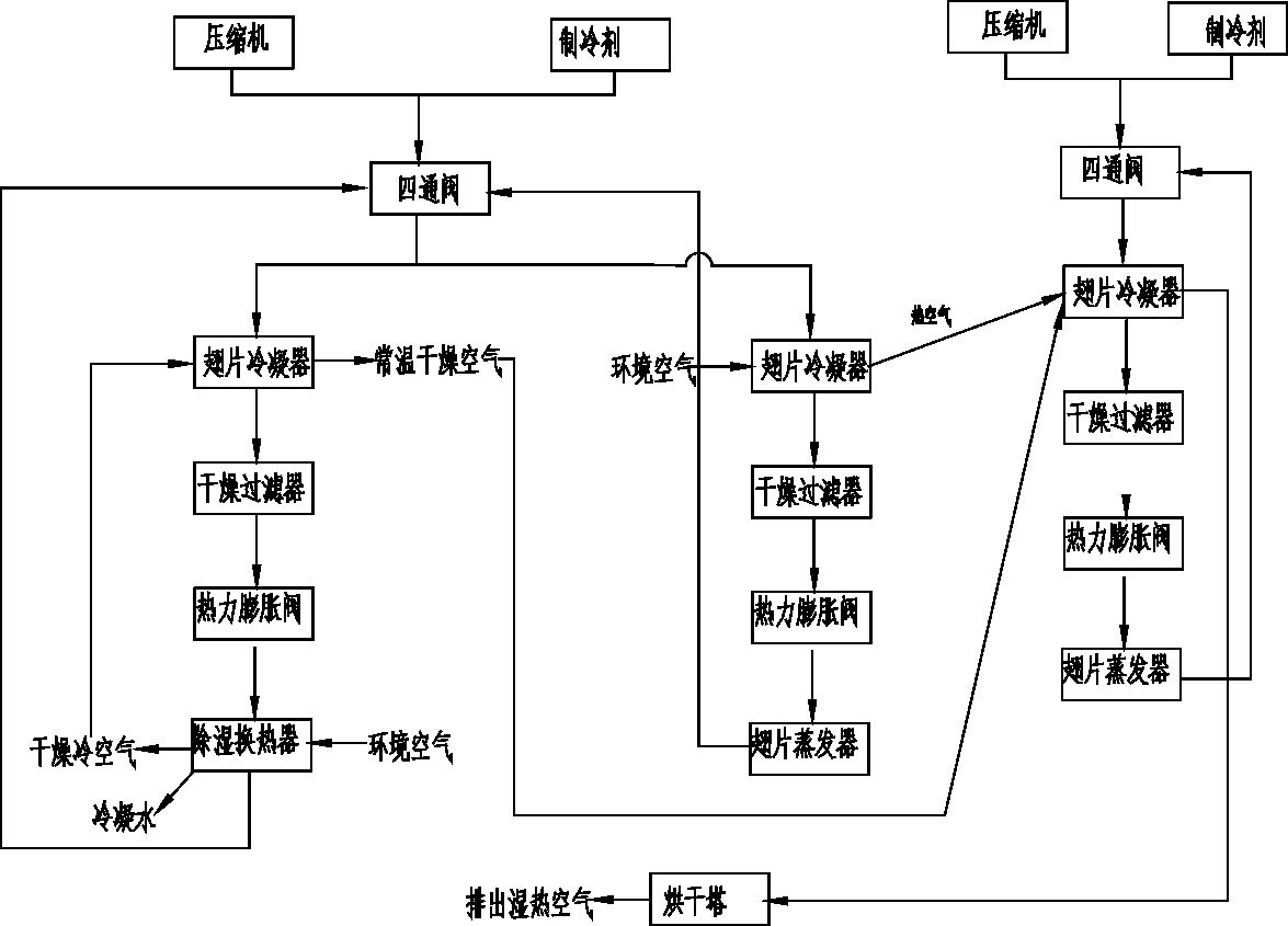
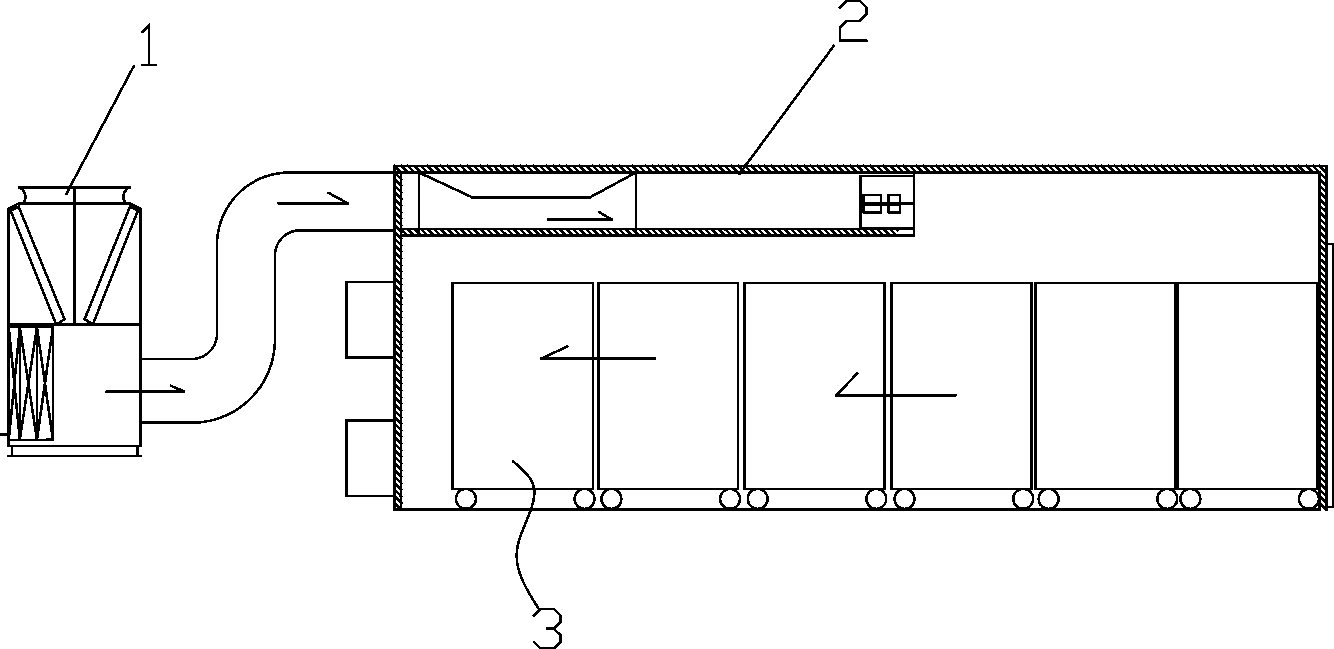
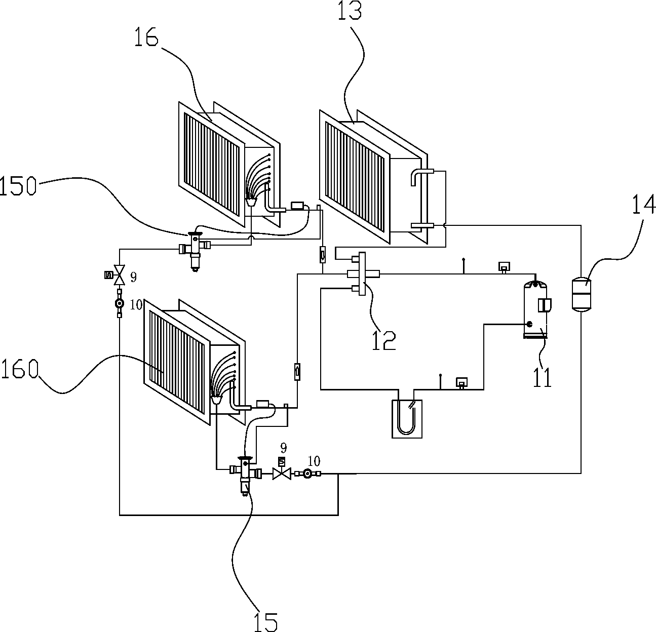
[0017] The present invention will be described in further detail below in conjunction with accompanying drawing and specific embodiment: see figure 1 , a grain drying process, characterized in that it includes the following steps: 1) loading the grain into a cart and sending it into a drying tower; 2) starting a heat pump drying unit connected to the drying tower, and the heat pump drying The compressor of the unit enters the high-temperature and high-pressure refrigerant gas into the condenser, and then throttles through the thermal expansion valve. The refrigerant becomes a low-temperature and low-pressure liquid and enters the dehumidification heat exchanger. Compressor, the ambient air is introduced into the air circulation pipeline by the fan, and first passes through the dehumidification heat exchanger to extract the moisture content in the air, and the dry cold air is heated to normal temperature air by the finned condenser to reduce the relative humidity of the air Pur...


PUM


Abstract

The invention discloses a grain drying technology. According to the grain drying technology, grain is dehumidified by a heat pump, and then dried, so that the grain drying technology has no pollution or combustion discharge, cannot injury a human body and has good social benefits.

Description

technical field [0001] The invention relates to a grain drying process. Background technique [0002] At present, the dryers mainly used in my country and the world mainly include "fuel oil-air supply", "wood burning-air supply" or other methods of directly burning energy or crops. [0003] "Fuel oil-air supply" and "wood burning-air supply" units are all fuel-based, which will increase smoke, CO, CO 2 This is not advisable under the condition that my country's atmospheric environment is seriously deteriorating and environmental protection requirements are becoming more and more important. The "fuel-air supply" process mainly uses diesel as fuel, which will compete with other industries for fuel, which will not only increase environmental pollution, but also increase the pressure on the country's energy supply. The "burning wood-air supply" process mainly uses straw, firewood, chaff, etc. as fuel, and these fuels pollute the environment more seriously. "Fuel oil-air suppl...

Claims


Application Information

Patent Timeline
Patent Type & Authority Applications(China)
IPC IPC(8): A23B9/08F26B21/02
CPCY02A40/90Y02P60/85
Inventor 祝富华郁志扬邹为奇
Owner 浙江天洲制冷机电有限公司
Why Eureka
Try Eureka