Dust blowing device for selective catalytic reduction (SCR) denitration reactor

A denitrification reactor and ash cleaning device technology, which is applied in the direction of chemical instruments and methods, dispersed particle separation, separation methods, etc., can solve the problems of insufficient soot blowing strength, difficulty in overcoming, and affecting denitrification efficiency, etc., achieving significant economic benefits and improving The effect of service life and improvement of denitrification efficiency

Inactive Publication Date: 2013-12-11
HUNAN LUNAN DESULFURIZATION & DENITRATION TECH
View PDF6 Cites 18 Cited by
  • Summary
  • Abstract
  • Description
  • Claims
  • Application Information

AI Technical Summary

Problems solved by technology

Steam rake cleaning uses steam as the soot blowing medium, which consumes a large amount of steam, and condensed water is produced due to a large amount of water precipitation during the soot blowing process, which affects the service life of the catalyst
Catalyst usage specifications require that the moisture in the flue gas must be less than 10%, and there is a hidden danger that the precipitation of steam moisture is higher than 10%.
In addition, the coverage of rake cleaning is insufficient, and the cleaning is not thorough, and there is still a large amount of ash remaining on the catalyst, which affects the denitrification efficiency.
Although the coverage of sonic cleaning is larger than that of rake cleaning, the blowing force is insufficient and the effect is poor.
Shock wave dust removal uses the shock wave and air wave soot blowing generated by the instantaneous explosion when the fuel is ignited. Due to the high temperature of 1000°C during the explosion, it seriously affects the life of the catalyst.
Because the maximum temperature that the catalyst can withstand is 450°C, the high-temperature catalyst at 1000°C cannot withstand it at all, and will be damaged and invalidated in a short period of time
To sum up, the traditional dust cleaning methods have major defects that are difficult to overcome.

Method used


Image

  • Dust blowing device for selective catalytic reduction (SCR) denitration reactor
  • Dust blowing device for selective catalytic reduction (SCR) denitration reactor
  • Dust blowing device for selective catalytic reduction (SCR) denitration reactor

Examples


Embodiment Construction

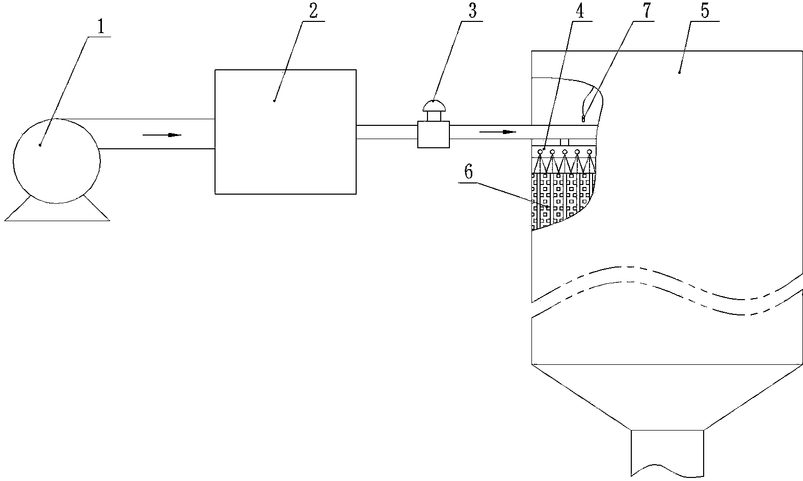
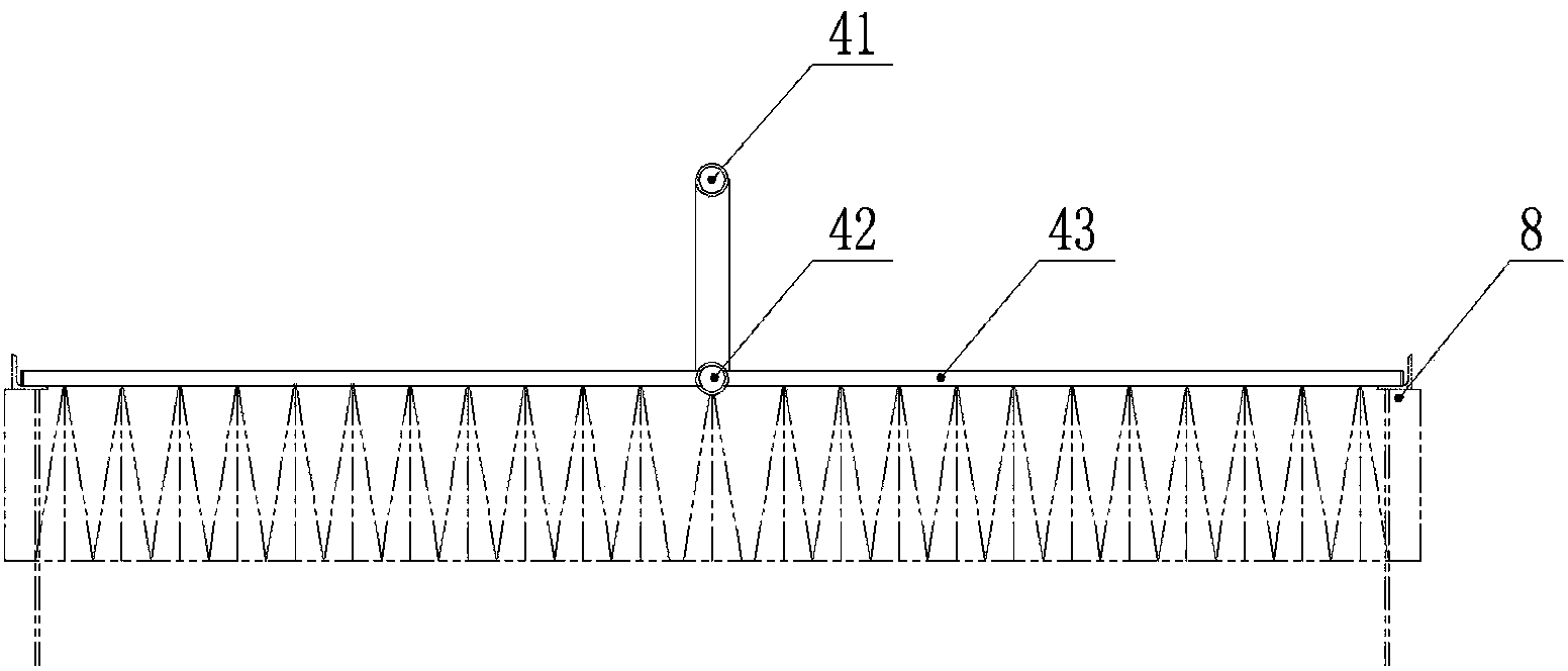
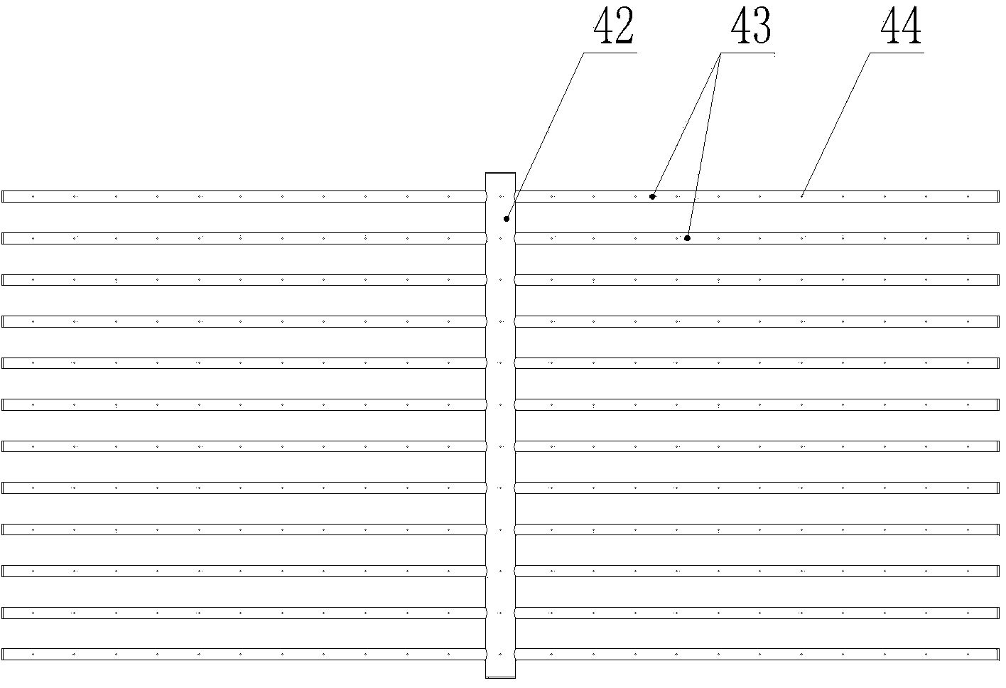
[0014] Such as Figure 1 to Figure 3 As shown, the soot blowing device for the SCR denitrification reactor disclosed by the present invention includes an air compressor 1, a buffer tank 2, a solenoid valve 3 and a soot blowing pipe network unit module 4, and the soot blowing pipe network unit module 4 is located in The top of the catalyst unit 6 in the SCR denitration reactor 5 is arranged in one-to-one correspondence with the catalyst unit 6 . The soot blowing pipe network unit module 4 includes an air supply main pipe 41 , a main air distribution conduit 42 and several air jet soot blowing branch pipes 43 . The main air distribution conduit 42 is connected to the bottom of the air supply main pipe 41, the air distribution branch pipes 43 are evenly distributed on the longitudinal sides of the main air distribution pipe 42, and the lower side of the air distribution soot blowing branch pipes 43 are evenly distributed with air injection holes 44. The compressed air outlet of ...


PUM


Abstract

The invention discloses a dust blowing device for a selective catalytic reduction (SCR) denitration reactor. The dust blowing device comprises an air compressor, a buffer tank, a solenoid valve and jet pipe network unit module which are communicated in sequence; the jet pipe network unit module is positioned on catalyst units positioned in the SCR denitration reactor and jet pipes in the jet pipe network unit module are in one-to-one correspondence with the catalyst units. In the dust blowing device, a dust blowing air source is provided for the jet pipe network unit module by utilizing the air compressor; compressed air is stored and released by utilizing the buffer tank; the opening and the closing of the buffer tank is controlled by utilizing the solenoid valve; the jet pipes which are in the jet pipe network unit module and are in one-to-one correspondence with the catalyst units blow away dust in a manner of being dead against catalysts. The dry compressed air serves as a dust blowing medium, so that the normal work of the catalyst in a dry state is guaranteed. The dust blowing device has no vibration, no high temperature, no dead angle or no gathered dust residue, and has a large coverage surface when the gathered dust is cleaned by the compressed air; the service life of the catalysts is prolonged; the replacement cycle of the catalysts is prolonged; the denitration efficiency is effectively improved; an energy resource is saved.

Description

[0001] technical field [0002] The invention relates to an SCR denitration reactor, in particular to a soot blowing device for the SCR denitration reactor. Background technique [0003] At present, there are five main methods of dust removal in traditional SCR denitrification reactors: mechanical rapping, sonic, steam rake, shock wave, and steel ball rolling. Among them, mechanical vibration cleaning and steel ball rolling cleaning are very easy to damage the catalyst due to the high vibration intensity, and the catalyst is broken due to strong external force, which is not advisable. Steam rake cleaning uses steam as the soot-blowing medium, which consumes a large amount of steam, and condensed water is generated due to a large amount of water precipitation during the soot-blowing process, which affects the service life of the catalyst. The specification for the use of catalysts requires that the moisture in the flue gas must be less than 10%, while the precipitation of st...

Claims


Application Information

Patent Timeline
Patent Type & Authority Applications(China)
IPC IPC(8): B01D53/90B01D53/96
Inventor 杨健
Owner HUNAN LUNAN DESULFURIZATION & DENITRATION TECH
Why Eureka
Try Eureka