
Lacing hole boss structure of turbine blade and matching structure for lacing hole boss structure and loose lacing wires

A steam turbine blade and boss structure technology, which is applied in the direction of blade support components, mechanical equipment, engine components, etc., can solve the problems of local wear of tie bars, poor damping effect, stuck holes of tie bars, etc., and achieve the alleviation of wear problems , The installation process is smooth, and the effect of reducing torsional vibration

Inactive Publication Date: 2013-12-11
XI AN JIAOTONG UNIV
View PDF8 Cites 2 Cited by
  • Summary
  • Abstract
  • Description
  • Claims
  • Application Information

AI Technical Summary

Problems solved by technology

[0004] From decades of research, design, processing, and operation experience of domestic and foreign scholars and engineers on steam turbine blades, there are several key issues when installing loose tie structures on blades to reduce vibration: First, the installation of loose tie bars, due to The loose tie bar is arc-shaped in space, and when it is inserted into the tie bar hole of the blade, there will often be stuck, friction and other phenomena that are not conducive to its installation; The damping caused by the contact between the tie bars and the blade is the essential reason for the vibration reduction of the blade, so it is necessary to ensure good contact between the tie bars and the blade, and to increase the contact points as much as possible; the third is the material selection of the loose tie bars due to the stress condition , wear of loose ties, etc. Since the stress of loose ties needs to be controlled, titanium alloys and other low-density materials with a small elastic modulus are often used, but their damping effect is poor. Part of the stress concentration phenomenon, after the blade has been running for a period of time, the local tendon often wears out

Method used


Image

  • Lacing hole boss structure of turbine blade and matching structure for lacing hole boss structure and loose lacing wires
  • Lacing hole boss structure of turbine blade and matching structure for lacing hole boss structure and loose lacing wires
  • Lacing hole boss structure of turbine blade and matching structure for lacing hole boss structure and loose lacing wires

Examples


Embodiment Construction

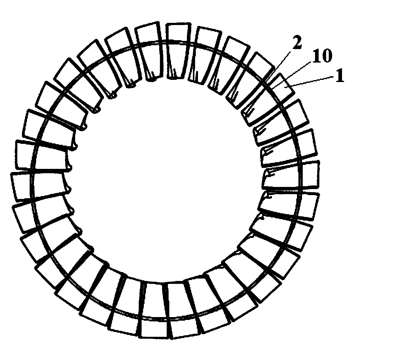
[0030] see figure 1 60%-80% of the blade height of the steam turbine motor blade 1 is a tie hole 10, and the loose tie 2 passes through the tie hole to connect the blades in a full circle.

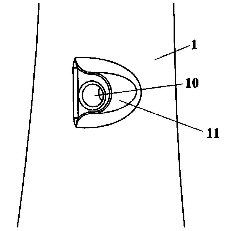
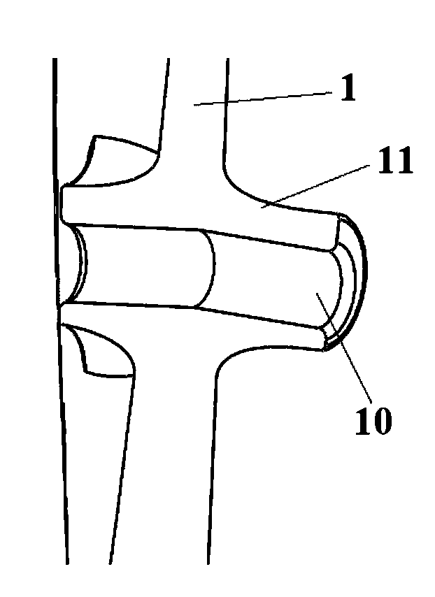
[0031] see Figure 2a , as shown in 2b, a boss structure of a steam turbine blade tension hole of the present invention, a boss is processed on the pressure side and the suction side of the blade 1, the boss 11 is horizontally extended, and its axis 110 is the circumference of the blade 1 In the direction, the sum of the protruding lengths of the pressure surface and the suction surface boss 11 of adjacent blades 1 is preferably 0.4-0.6 times the blade pitch. A tie hole 10 is arranged in the boss 11 so that the tie bar 2 penetrates, and the relative angle between the center line 100 of the tie hole and the center line 110 of the boss is shown in Figure 2c , taking the pitch circle diameter of the tie bar 2 as the standard, the tie bar hole 10 is inclined to both sides, and forms an angl...


PUM


Abstract

The invention discloses a lacing hole boss structure of a turbine blade and a matching structure for the lacing hole boss structure and loose lacing wires. The lacing hole boss structure comprises blades and loose lacing wires, wherein pressure sides and suction sides of the blades are provided with bosses respectively; the bosses horizontally extend out from the pressure sides and the suction sides of the blades; the boss axis of the bosses is the circumferential direction of the blades; the sum of extension lengths of the pressure side bosses and the suction side bosses of adjacent blades is 0.4-0.6 times the blade pitch; lacing holes are formed in the bosses; the included angle between the central line of each lacing hole and the boss axis is 2-4 degrees; the loose lacing wires are arranged in the lacing holes in a penetrating manner; during working of the blades, each loose lacing wire is in contact with each lacing hole of each pressure side boss and each lacing hole of each suction side boss to form two contact points, so that the total vibration damping is increased and the vibration reduction capacity of the loose lacing wires to the blades is improved; meanwhile, the two contact points can form torque during blade torsion, so that the torsional vibration of the blades produced during work can be weakened.

Description

technical field [0001] The invention belongs to the field of turbine machinery, and relates to a tendon-stretching device for turbine blades. Background technique [0002] Turbine machinery is an important power machinery in the fields of energy, chemical industry and national defense. The blade is the most important element for the mutual transformation of thermal energy and mechanical energy when the turbine machinery (such as a steam turbine) is working. The lacing structure is often used in the steam turbine blades to reduce blade vibration. A kind of method, the tie bar structure includes two types of boss tie bars and loose tie bars. [0003] Steam turbine blades will generate certain vibrations during operation. Blade vibration is often the most common and direct cause of damage to blades. Therefore, blade designers pay great attention to the vibration characteristics and vibration reduction structure of blades. There are usually two main methods to reduce blade vibra...

Claims


Application Information

Patent Timeline
IPC IPC(8): F01D5/16
Inventor 谢永慧申仲旸张荻
Owner XI AN JIAOTONG UNIV
Learn More