
Fly ash separating and conveying system of economizer

A fly ash separation and conveying system technology, applied in the direction of combustion product treatment, combustion method, solid residue removal, etc., can solve the problems of thermal storage element wear, increased power consumption rate of induced draft fan, increased heat loss of exhaust smoke, etc. Achieve the effects of enhancing the uniformity of the flow field, reducing the concentration of fly ash, and reducing the concentration of emissions

Active Publication Date: 2013-12-11
HUADIAN ELECTRIC POWER SCI INST CO LTD
View PDF7 Cites 0 Cited by
  • Summary
  • Abstract
  • Description
  • Claims
  • Application Information

AI Technical Summary

Problems solved by technology

[0002] Due to the tight supply and demand of coal, the fuel used by large coal-fired generating units deviates greatly from the design value, the calorific value of coal is low, and the ash content increases, resulting in an increase in the proportion of fly ash in the flue gas after coal combustion, especially large particles, especially in domestic Some boilers designed to burn low-ash coals did not design the economizer ash hopper at the beginning of the design and the faulty unit of the economizer ash hopper conveying system. After the increase of large particles of fly ash in the flue gas during operation, the heat storage element of the air preheater After the unit has been running for a period of time, the heat storage element of the upper hot-end air preheater is worn and broken into pieces, and then falls off from the gap of the lower heat storage element. After the damaged heat storage element enters the middle heat storage element layer, it will The blockage of the flue gas passage leads to an increase in the resistance of the air preheater, and the part of the unblocked heat storage element area forms a flue gas corridor, which aggravates the wear of the heat storage element in this area, and finally leads to a decrease in the heat transfer capacity of the air preheater heat storage element and an increase in resistance , the boiler exhaust temperature increases, the exhaust heat loss increases, and the power consumption rate of the induced draft fan increases, which affects the safe, economical and efficient operation of the unit
The fly ash concentration in the actual flue gas of large thermal power units currently in operation is higher than the design inlet fly ash concentration of the electrostatic precipitator, resulting in the actual dust removal efficiency of the electrostatic precipitator not meeting the environmental protection requirements of less than 20mg / Nm 3 , in order to meet the requirements of environmental protection, large-scale generator sets are now undergoing transformation of electric bag dust collectors. The transformation of electric bag dust collectors not only increases the resistance of the flue gas system by more than 1000Pa, but also needs to be equipped with induced draft fans to increase the capacity, and also increases the operating costs of electric dust removal.
The large-particle fly ash of the economizer designed by the existing unit is first separated into the ash hopper of the economizer, and then transported to the ash storage through the warehouse pump. , blockage, resulting in failure of the ash conveying system of the economizer, and the large particles of fly ash in the flue gas cannot be effectively separated

Method used


Image

  • Fly ash separating and conveying system of economizer

Examples


Embodiment Construction

[0017] The present invention will be further described in detail below in conjunction with the accompanying drawings and examples. The following examples are explanations of the present invention and the present invention is not limited to the following examples.

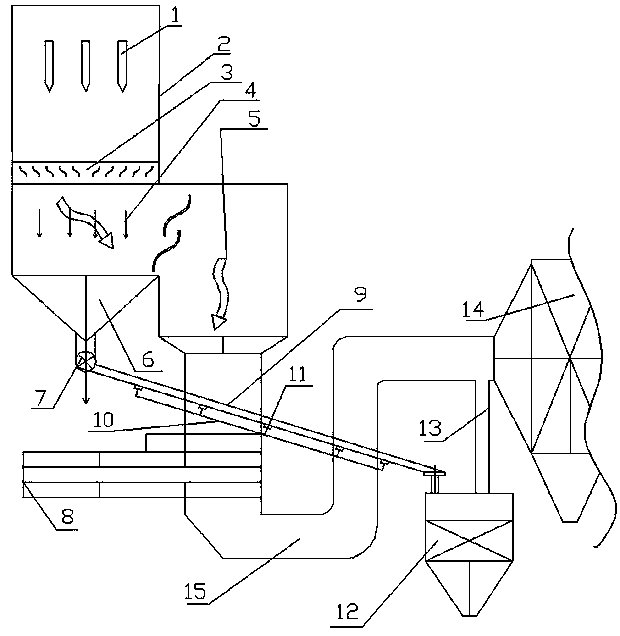
[0018] see figure 1 , The embodiment of the present invention includes an ash hopper separation device 2 , an air preheater 8 , a fly ash conveying trough 9 , an ash storage 12 , a connecting channel 13 , and an electrostatic precipitator 14 .

[0019] The ash hopper separation device 2 includes a corrugated plate device 3 , a corrugated plate 4 , an ash hopper 6 and an ash discharge device 7 . The corrugated plate device 3 is fixedly installed in the vertical flue 1, and a wave-shaped corrugated plate 4 is arranged on the corrugated plate device 3, and the corrugated plate 4 is arranged symmetrically. Just below the plate device 3, the ash discharge device 7 is arranged below the ash hopper 6; The structure of th...


PUM

PropertyMeasurementUnit
Diameteraaaaaaaaaa

Abstract

The invention relates to a fly ash separating and conveying system of an economizer, which is used in a fly ash separating technique for tail smoke from a large-scale power plant boiler. One end of an air preheater outlet flue is communicated with a smoke outlet of an ash hopper separating device, and the other end of the air preheater outlet flue is communicated with an electric dust collector; a fly ash conveying groove is arranged in an inclined mode, one end of the fly ash conveying groove is communicated with an ash discharging device, and the other end of the fly ash conveying groove is communicated with an ash storage warehouse; the fly ash conveying groove comprises an air inclined groove and a disturbance wind device, fly ash disturbance holes are respectively formed in both sides of the bottom of the fly ash conveying groove, one end of each fly ash disturbance hole is communicated with the air inclined groove, and the other end of each fly ash disturbance hole is communicated with the disturbance wind device; the disturbance wind device is communicated with a hot secondary air pipeline of an air preheater outlet; one end of a connecting channel is communicated with the ash storage warehouse, and the other end of the connecting channel is communicated with the electric dust collector. By using the fly ash separating and conveying system, large-particle fly ash in the tail smoke generated by boiler burning can be separated from mainstream smoke, and the separated fly ash can be safely, environment-friendly and efficiently conveyed to a safe place.

Description

technical field [0001] The invention relates to a fly ash separation and conveying system for an economizer, which is used in the separation technology of fly ash in the tail flue gas of a large-scale power station boiler. Background technique [0002] Due to the tight supply and demand of coal, the fuel used by large coal-fired generating units deviates greatly from the design value, the calorific value of coal is low, and the ash content increases, resulting in an increase in the proportion of fly ash in the flue gas after coal combustion, especially large particles, especially in domestic Some boilers designed to burn low-ash coals did not design the economizer ash hopper at the beginning of the design and the faulty unit of the economizer ash hopper conveying system. After the increase of large particles of fly ash in the flue gas during operation, the heat storage element of the air preheater After the unit has been running for a period of time, the heat storage element...

Claims


Application Information

Patent Timeline
IPC IPC(8): F23J3/02
Inventor 郑文广陈剑孙科秦鹏郝建刚吴桂福司顺勇
Owner HUADIAN ELECTRIC POWER SCI INST CO LTD
Learn More