Wavelength measurement method and device based on laser synthesized wavelength interference principle

A technology of laser synthesis and synthesis of wavelengths, which is applied in measuring devices, optical radiation measurement, and measuring optics. It can solve the problems of poor anti-interference ability of mechanical vibration, complex and invariable measurement system structure, etc., and achieve strong anti-environmental interference ability, Increased measurement range and high measurement accuracy

Inactive Publication Date: 2013-12-11
ZHEJIANG SCI-TECH UNIV
View PDF7 Cites 16 Cited by
  • Summary
  • Abstract
  • Description
  • Claims
  • Application Information

AI Technical Summary

Problems solved by technology

The Fabry-Perot interferometric wavelength meter uses the method of multi-beam interference when the beam passes through two parallel glass plates coated with high reflectivity and a fixed distance to measure the wavelength of the laser to be measured. The measurement accuracy can reach 10 -9 , but the wavelength measurement range is narrow
The Fizeau wavelength meter is a kind of thin-film double-beam interference. After the incident light enters the etalon, the front and rear reflective surfaces return two beams of light and generate interference fringes. The measurement of the laser wavelength to be measured is realized by calculating the periodic interval of the fringes. This method Although there is no need for a reference laser and the structure is simple, due to the poor anti-interference ability of the system to environmental temperature changes and mechanical vibrations, frequent calibration is required during the measurement process, which brings no change to the use.
The Michelson wavelength meter calculates the wavelength of the light to be measured by calculating the ratio of the number of interference fringes between the reference light and the light to be measured, that is, N R N U =λ U lambda R (wherein, N R is the number of interference fringes of the reference laser, N U is the number of interference fringes of the laser to be measured, λ U is the wavelength of the laser to be measured, λ R for the wavelength of the reference laser), this method can achieve 10 -7 ~10 -8 However, in order to improve the measurement accuracy, it is necessary to increase the range of motion of the guide rail or to subdivide the interference signal with high precision, which will make the structure of the measurement system complex and costly
In addition, the laser wavelength measurement method based on the synthetic wavelength is to detect the laser wavelength λ to be measured U and the reference laser wavelength λ R The resulting synthetic wavelength λ S value, to achieve the laser wavelength λ to be measured U measurement, but this method is when the wavelength of the laser to be measured λ U with reference laser wavelength λ R When very close, the resulting synthetic wavelength λ S It will be very large and will far exceed the range of motion of the guide rail where the measuring mirror moves, so the measurement range of the laser wavelength to be measured is small and limited by the range of motion of the guide rail

Method used


Image

  • Wavelength measurement method and device based on laser synthesized wavelength interference principle
  • Wavelength measurement method and device based on laser synthesized wavelength interference principle
  • Wavelength measurement method and device based on laser synthesized wavelength interference principle

Examples


Embodiment Construction

[0023] The present invention will be further described below in conjunction with the accompanying drawings and embodiments.

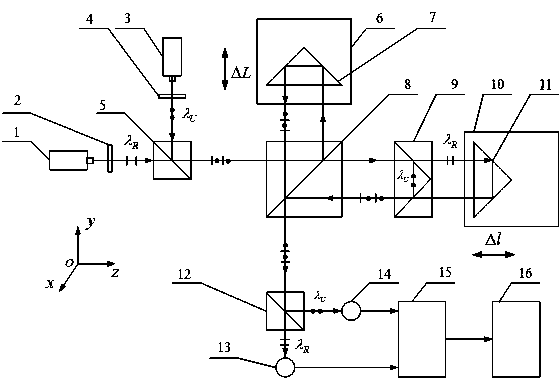
[0024] A wavelength measurement method and device based on the principle of laser synthesis wavelength interference, such as figure 1 As shown, the beam output by the reference laser 1 passes through the first polarizer 2 whose transmission direction is parallel to the y-axis, and then becomes linearly polarized light λ parallel to the y-axis R , to the first polarizing beam splitter 5; the light beam output by the laser to be measured 3 passes through the second polarizer 4 whose transmission direction is parallel to the x-axis, and becomes linearly polarized light λ parallel to the x-axis U , to the first polarizing beam splitter 5; linearly polarized light λ R Through the first polarizing beam splitter 5 and the linearly polarized light λ U After being reflected by the first polarizing beam splitter 5, a bundle of orthogonal linearly polarized ligh...


PUM


Abstract

The invention discloses a wavelength measurement method and device based on a laser synthesized wavelength interference principle. An output beam of a reference laser device and an output beam of a laser device to be measured are modulated into orthogonal linearly polarized light which is emitted to a laser synthesized wavelength interferometer to form an interference signal of the reference laser device and an interference signal of the laser device to be measured; when a first pyramid prism of the interferometer moves, a phase difference change 2pi of the two interference signals corresponds to the displacement of the first pyramid prism when the first pyramid prism shifts by a half of a synthesized wavelength lambada S formed by a reference laser wavelength lambada R and a laser wavelength to be measured lambada U; when the lambada S is small, the position where the two interference signals pass by a zero point simultaneously for twice is detected to obtain the value of the lambada S; when the lambada S is large, a second pyramid prism is moved first, the position where the two interference signals pass by the zero point simultaneously for twice is detected, and then the value of the lambada S is obtained in combination with the corresponding relation between displacement of the second pyramid prism and the displacement of the first pyramid prism; lastly, the value of the laser wavelength to be measured is obtained according to the relation between the lambada U and the lambada S and the relation between the lambada R and the lambada S. The wavelength measurement method and device based on the laser synthesized wavelength interference principle are wide in laser wavelength measurement range, strong in resistance to environmental disturbance, and high in wavelength measurement accuracy.

Description

technical field [0001] The invention relates to a laser wavelength measurement method and device, in particular to a wavelength measurement method and device based on the principle of laser synthesis wavelength interference. Background technique [0002] In the field of laser technology research and application, the precise measurement and calibration of laser wavelength has important scientific significance and practical engineering value. In the technical field of measuring geometric quantities such as length, speed, angle, distance, and surface topography, a large number of frequency-stabilized lasers are used as coherent light sources for interferometry. The laser wavelength is used as a ruler for measuring geometric quantities. Wavelength is the key to ensure the accuracy of geometric measurement and the traceability of the value; in laser communication, the coherent heterodyne method is usually used to receive optical signals, and the stability of laser wavelength is o...

Claims


Application Information

Patent Timeline
Patent Type & Authority Applications(China)
IPC IPC(8): G01J9/02
Inventor 陈本永严利平田秋红刘燕娜楼盈天
Owner ZHEJIANG SCI-TECH UNIV
Why Eureka
Try Eureka