
Multi-channel laser absorption spectrum measuring system

A laser absorption spectrum and measurement system technology, applied in the field of multi-channel laser absorption spectrum measurement system, can solve the problems of long test time, low laser intensity, optical path disturbance, etc., and achieve the effect of simplifying operation and reducing difficulty

Inactive Publication Date: 2013-12-11
TSINGHUA UNIV
View PDF13 Cites 3 Cited by
  • Summary
  • Abstract
  • Description
  • Claims
  • Application Information

AI Technical Summary

Problems solved by technology

Second, due to the energy saturation of laser absorption, the laser intensity is often low when measuring the metastable state, and the laser intensity is relatively high when measuring the resonance state, so the detector needs to have adjustable sensitivity to adapt to different experiments. Intensity Sensitivity Requirements
The optical path of laser light is extremely precise. Replacing the laser may disturb the light path and cause measurement errors.
Moreover, the test time is longer due to the operation of replacing the laser, which will also affect the authenticity of the measurement results.
Furthermore, in the prior art, the time resolution and sensitivity of the measuring device are fixed, which cannot be applied to all tested particles, which often brings large errors to the

Method used


Image

  • Multi-channel laser absorption spectrum measuring system
  • Multi-channel laser absorption spectrum measuring system
  • Multi-channel laser absorption spectrum measuring system

Examples


Embodiment Construction

[0022] Embodiments of the present invention are described in detail below, examples of which are shown in the drawings, wherein the same or similar reference numerals designate the same or similar elements or elements having the same or similar functions throughout. The embodiments described below by referring to the figures are exemplary and are intended to explain the present invention and should not be construed as limiting the present invention.

[0023] Combine below Figure 1 to Figure 3 The multi-channel laser absorption spectroscopy measurement system of the present invention is introduced.

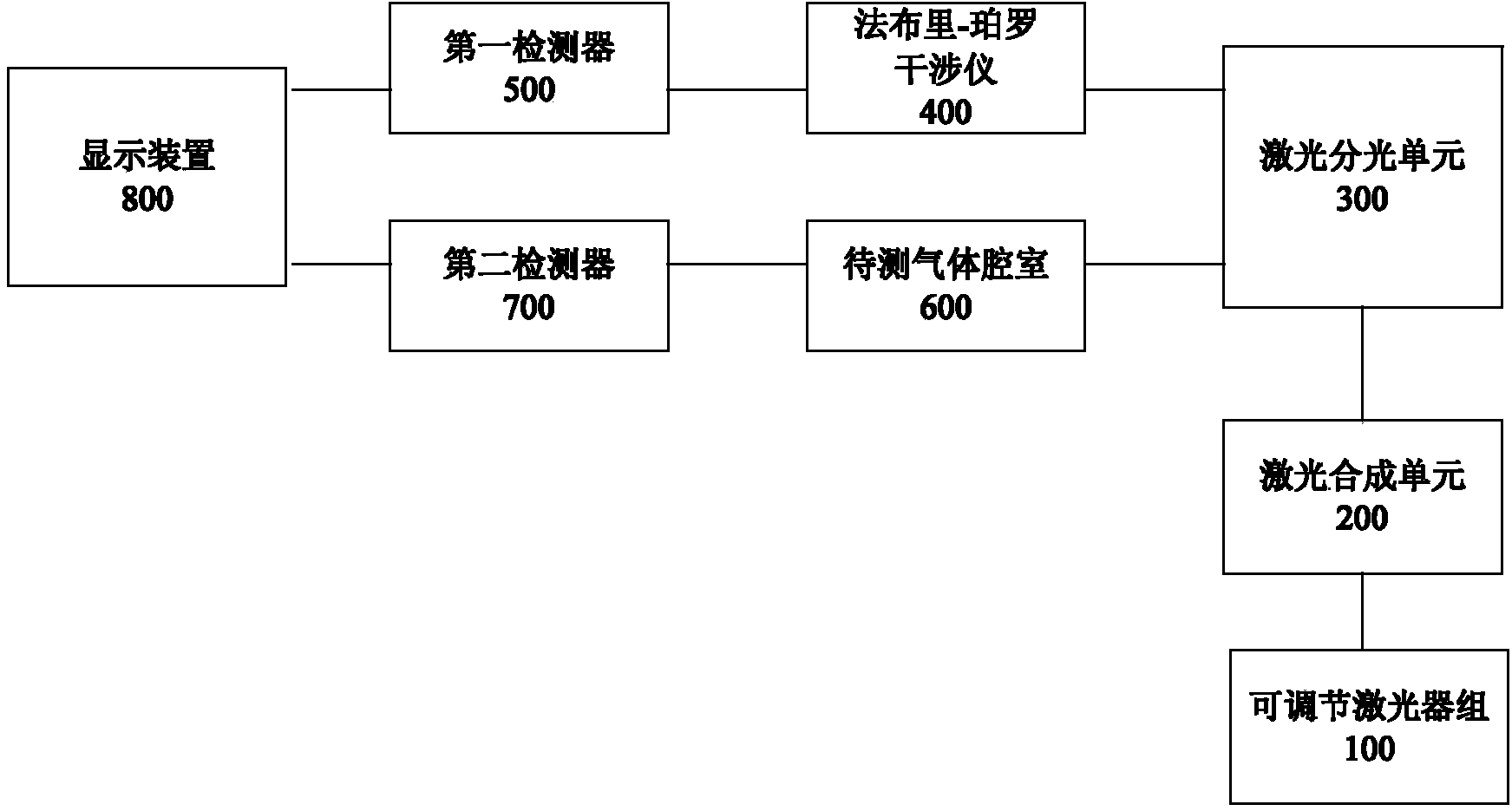
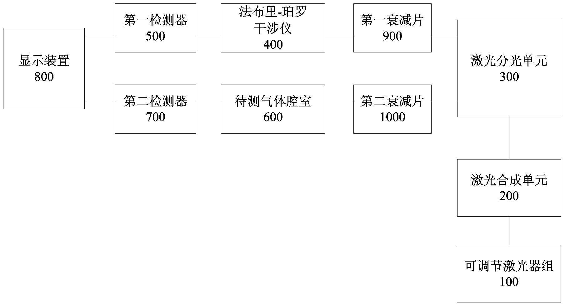
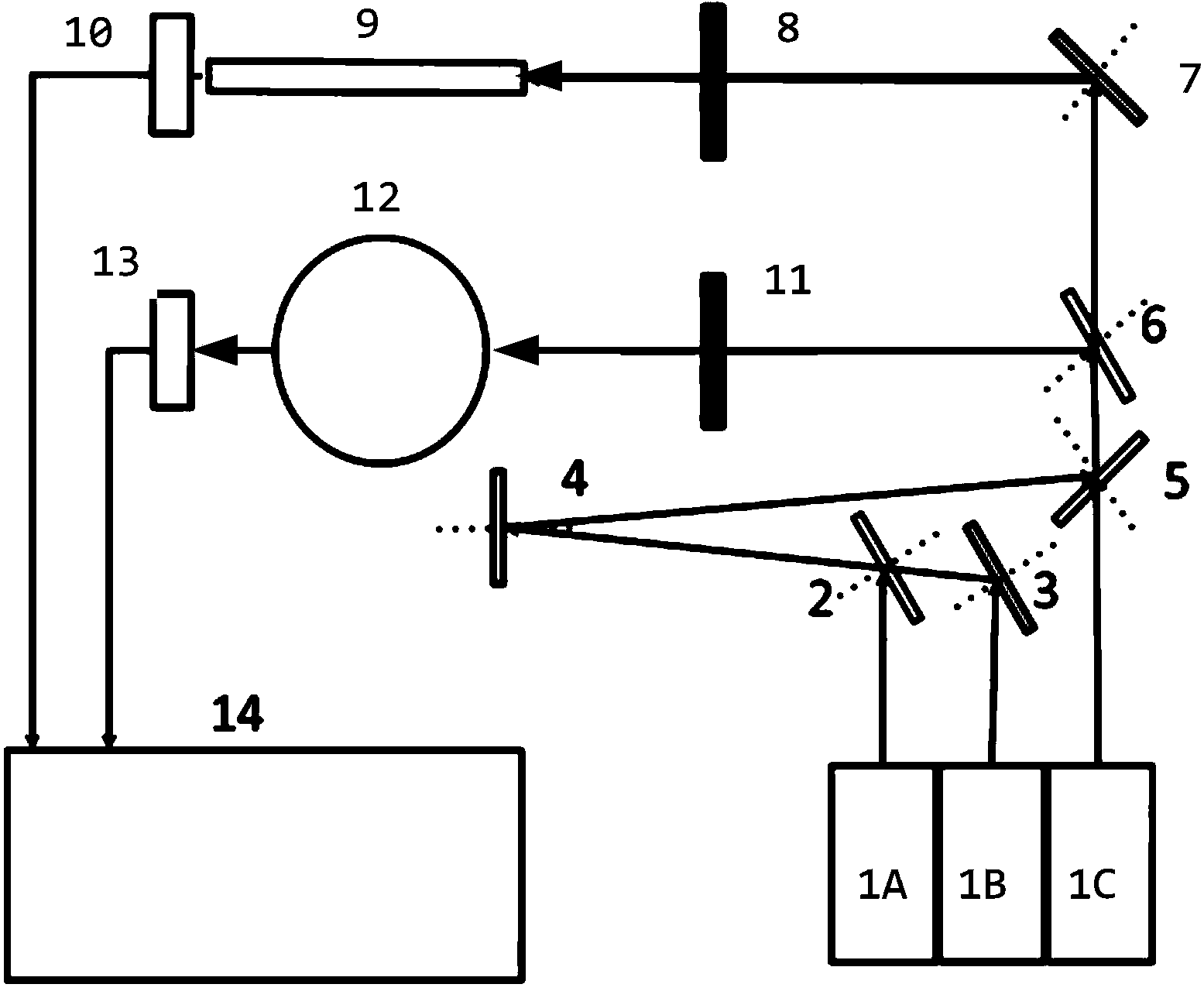
[0024] Such as figure 1 As shown, the multi-channel laser absorption spectroscopy measurement system in Embodiment 1 of the present invention may include: an adjustable laser group 100, a laser combining unit 200, a laser spectroscopic unit 300, a Fabry-Perot interferometer 400, and a first detector 500 , the gas chamber 600 to be tested, the second detector 700 and the display ...


PUM

PropertyMeasurementUnit
Wavelengthaaaaaaaaaa

Abstract

The invention discloses a multi-channel laser absorption spectrum measuring system. The measuring system comprises an adjustable laser device group, a laser synthesis unit, a laser dividing unit, a Fabry-Perot interferometer, a first detector, a to-be-detected gas cavity, a second detector and a display device, wherein the adjustable laser device group comprises multiple adjustable laser devices; the laser synthesis unit is used for converging lasers sent from the multiple adjustable laser devices into a synthesized laser beam; the laser dividing unit is used for dividing the synthesized laser beam sent from the laser synthesis unit into a first laser beam and a second laser beam which are the same; the Fabry-Perot interferometer is used for laser frequency calibration; the first detector is positioned at the rear end of the Fabry-Perot interferometer and is used for detecting the intensity of the first laser beam passing through the Fabry-Perot interferometer; the to-be-detected gas cavity is used for containing to-be-detected gas; the second detector is positioned at the rear end of the to-be-detected gas cavity and is used for detecting the intensity of the second laser beam passing through the to-be-detected gas cavity; the display device is used for displaying a detection result. The measuring system has the advantages of large coverage range of adjustable output laser wave length, no frequent replacement of optical paths in the use of the measuring system, and the like.

Description

technical field [0001] The invention relates to the field of optical instruments, in particular to a multi-channel laser absorption spectrum measurement system. Background technique [0002] For the study of the dynamics of particles in low-temperature plasmas, optical diagnostic methods are usually used to obtain the particle number density of target excited state particles. In order to obtain the particle number density of the luminous energy level, the density of the luminous upper energy level is usually obtained by observing the luminous intensity of the plasma. For the particle number density of the lower energy level of the luminescent energy level, the optical absorption method is often used, that is, the particle number density of the lower energy level is judged by observing the absorption of the lower energy level particles in the plasma to the light of the corresponding wavelength. Therefore, the absorption spectrum method requires external The light source emit...

Claims


Application Information

Patent Timeline
IPC IPC(8): G01N21/39
Inventor 程治文蒲以康
Owner TSINGHUA UNIV
Learn More