

Light spot homogenizing device and manufacturing method thereof
A manufacturing method and technology of a homogenizer, which are applied to lasers, laser parts, semiconductor lasers, etc., can solve the problems of uneven output light spots of semiconductor lasers, and achieve the effects of solving uneven output light spots, being easy to implement, and preventing damage.
- Summary
- Abstract
- Description
- Claims
- Application Information
AI Technical Summary
Problems solved by technology
Method used
Image

Examples
Embodiment 1
[0024] A method for manufacturing a spot homogenizer, comprising the following steps:
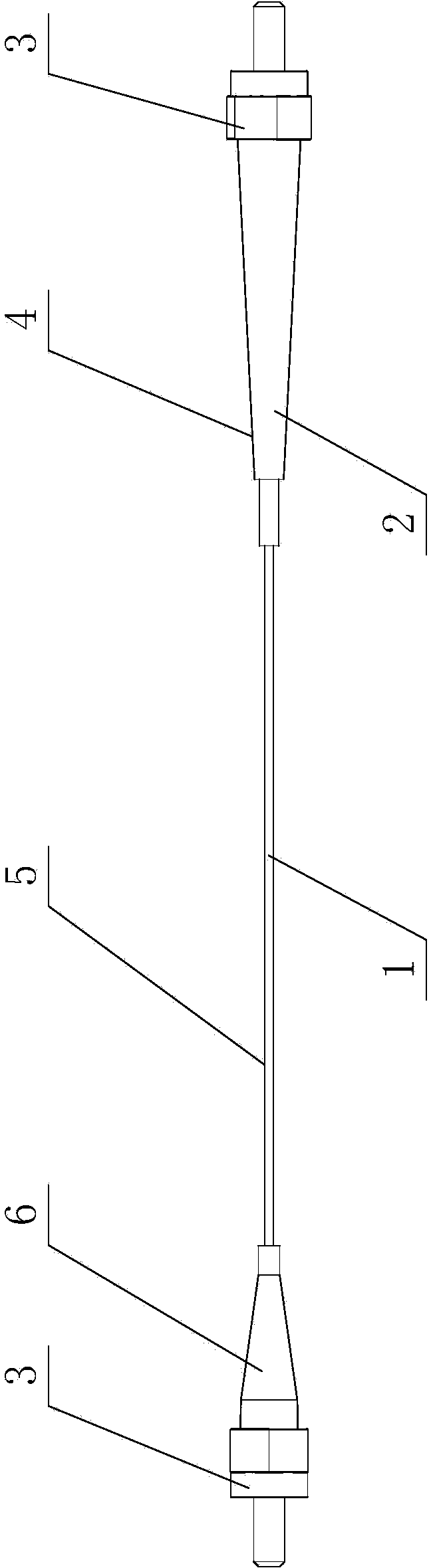
[0025] a. Use wire strippers to strip the coating layer on the optical fiber 1, and the length of the optical fiber 1 after stripping the coating layer is 4cm;
[0026] b. Use an optical fiber fusion splicer to heat-treat the portion of the optical fiber 1 from which the coating has been stripped, at a temperature of 1300°C, so that the optical fiber 1 from which the coating has been stripped reaches a molten state, and then wait for it to cool naturally;
[0027] c. Put an optical fiber sheath 5 on the entire optical fiber 1;
[0028] d. Put an optical fiber tail sleeve 6 on the output end of the optical fiber 1;
[0029] e, adopting the optical fiber heat shrinkable tube 4 to fix the optical fiber 1 of the heat treatment part;
[0030] f. Install an optical fiber jumper 3 at the input end and output end of the optical fiber 1.
[0031] The spot homogenizer manufactured by this method h...
Embodiment 2
[0033] A method for manufacturing a spot homogenizer, comprising the following steps:
[0034] a. Use wire strippers to strip the coating layer on the optical fiber 1, and the length of the optical fiber 1 after stripping the coating layer is 5 cm;
[0035] b. Use an optical fiber fusion splicer to heat-treat the portion of the optical fiber 1 that has been stripped of the coating layer at a temperature of 1400°C, so that the optical fiber 1 that has been stripped of the coating layer reaches a molten state, and then cool it down naturally;
[0036] c. Put an optical fiber sheath 5 on the entire optical fiber 1;
[0037] d. Put an optical fiber tail sleeve 6 on the output end of the optical fiber 1;
[0038] e, adopting the optical fiber heat shrinkable tube 4 to fix the optical fiber 1 of the heat treatment part;
[0039] f. Install an optical fiber jumper 3 at the input end and output end of the optical fiber 1.
[0040] The light spot homogenizer manufactured by this met...
Embodiment 3
[0042] A method for manufacturing a spot homogenizer, comprising the following steps:
[0043] a. Use wire strippers to strip the coating layer on the optical fiber 1, and the length of the optical fiber 1 after stripping the coating layer is 6cm;
[0044] b. Use an optical fiber fusion splicer to heat-treat the portion of the optical fiber 1 that has been stripped of the coating layer, at a temperature of 1500 ° C, so that the optical fiber 1 that has been stripped of the coating layer reaches a molten state, and then wait for it to cool naturally;
[0045] c. Put an optical fiber sheath 5 on the entire optical fiber 1;
[0046] d. Put an optical fiber tail sleeve 6 on the output end of the optical fiber 1;
[0047] e, adopting the optical fiber heat shrinkable tube 4 to fix the optical fiber 1 of the heat treatment part;
[0048] f. Install an optical fiber jumper 3 at the input end and output end of the optical fiber 1.
[0049] The spot homogenizer manufactured by this ...
PUM
| Property | Measurement | Unit |
|---|---|---|
| Fiber length | aaaaa | aaaaa |
| Length | aaaaa | aaaaa |
| Length | aaaaa | aaaaa |
Abstract
Description
Claims
Application Information