
High-luminance LED strobe lamp

A technology of LED strobe lights and LED lights, which is applied in the direction of electric lamp circuit layout, lighting devices, light sources, etc., can solve the problems of reduced lifespan, high calorific value, poor lighting effect, etc., and achieve high power consumption and strong compatibility Effect

Active Publication Date: 2013-12-11
南京大为智能科技有限公司
View PDF7 Cites 14 Cited by
  • Summary
  • Abstract
  • Description
  • Claims
  • Application Information

AI Technical Summary

Problems solved by technology

The existing road monitoring supplementary light equipment used in the field of intelligent transportation mainly uses two methods: constant supplementary light and burst supplementary light. However, the constant supplementary light mode has low brightness, poor supplementary light effect, high power consumption, and high heat generation. , it is easy to cause serious LED light attenuation and greatly reduce its lifespan, which cannot meet the requirements of road monitoring; strobe fill light is only fill light when the camera needs to capture images, flickering like lightning, resulting in serious light pollution
Moreover, the two supplementary light methods are relatively simple, and cannot realize continuous supplementary light and high-brightness capture flash at the same time, and cannot meet the supplementary light requirements for continuous capture of road violations and the requirements for capturing pictures with high quality requirements

Method used


Image

  • High-luminance LED strobe lamp
  • High-luminance LED strobe lamp
  • High-luminance LED strobe lamp

Examples


Embodiment 1

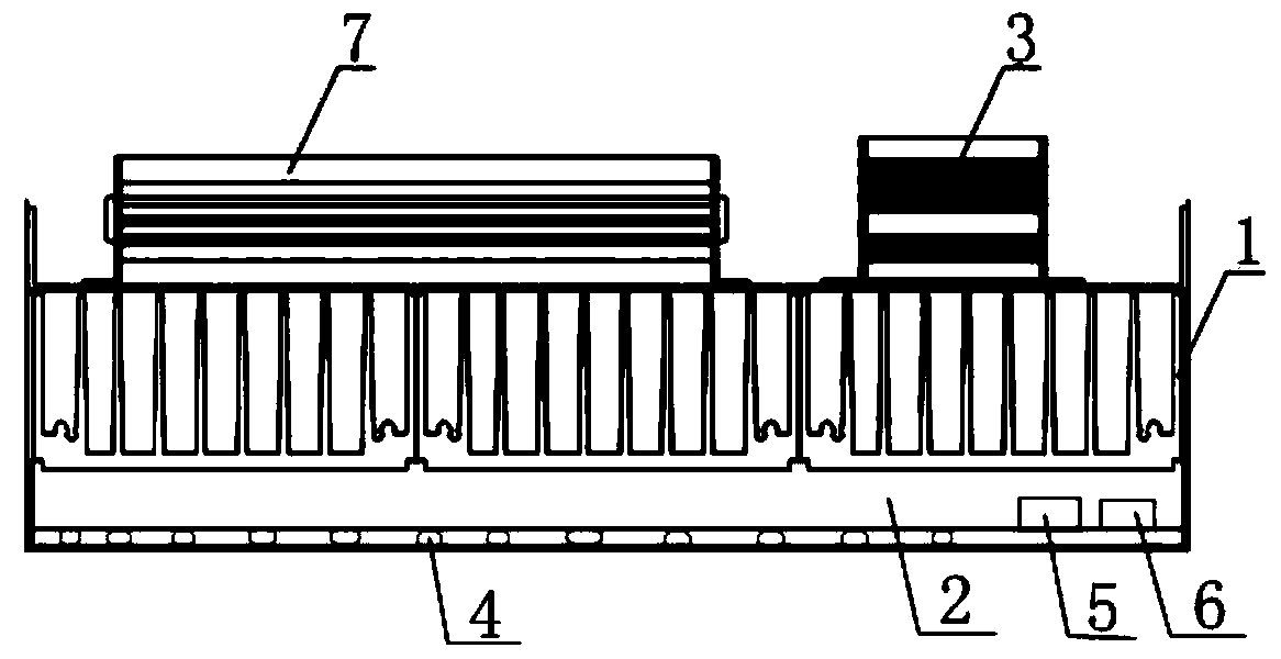
[0030] The present invention relates to a high-brightness LED strobe light. The energy-saving LED supplementary light provided in this embodiment is as follows: figure 1 As shown, it includes a lamp housing 1 and an LED aluminum substrate 2 arranged at the end of the lamp housing 1. The rear of the lamp housing 1 is provided with a switching power supply 7 and a strobe controller 3; High-power LED lamp beads, constant current drive module 4, photodiodes 5 and thermistors 6, each group of LED lamp beads 4 are connected in parallel with TVS transient voltage suppression diodes and series PTC resettable fuses.

[0031] The energy-saving LED supplementary light adopts a photosensitive diode as the brightness detection element of the present invention, and the photosensitive diode can be placed in front of the lamp housing without punching a photosensitive element at the rear of the lamp body like the existing supplementary light. The fast response of the photodiode can distinguish...


PUM


Abstract

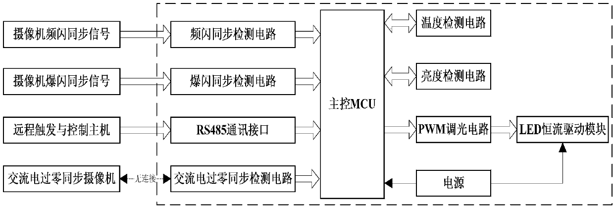
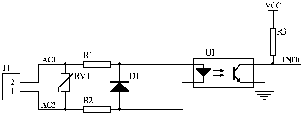
The invention relates to a high-luminance LED strobe lamp and belongs to the technical field of light source control. The high-luminance LED strobe lamp comprises a strobe / burst-strobe synchronous detection circuit. A port of a wiring terminal J2 in the circuit is respectively connected with a positive electrode and a negative electrode of a transient voltage suppression diode TVS1; the positive electrode of the transient voltage suppression diode TVS1 is connected in series with a diode D2 and then connected with an emitter of a triode Q1, and meanwhile the positive electrode of the transient voltage suppression diode TVS1 is connected with a resistor R8 in series and then connected with a base of a triode Q3; a base of the triode Q1 is connected with a resistor in series and then connected with a base of a triode Q2, both a collector of the triode Q1 and a collector of the triode Q3 are connected with an input port of a photoelectric coupler U2, and an output port of the photoelectric coupler U2 is connected with an input port of a master controller; a collector of the triode Q2 is connected with the base of the triode Q3, and an emitter of the triode Q2 and an emitter of the triode Q3 are connected and meanwhile grounded. A strobe control circuit controls strobe and burst strobe of the LED lamp, and thus the utilization rate of the light source and the quality of a snapshot photo are improved.

Description

technical field [0001] The invention belongs to the technical field of light source control, and relates to an LED lamp, in particular to a high-brightness LED strobe lamp with a good synchronization rate effect with peripheral devices. Background technique [0002] In a low-light environment, the synchronization noise of the camera's photosensitive element is very large. In the field of video surveillance, in order to obtain better image quality in low-light environments, auxiliary light sources are generally used to illuminate the shooting area. The auxiliary light source can be divided into three types: constant fill light, strobe fill light, and strobe fill light. Due to the advantages of low power consumption, long service life, high brightness, and durability, LED lights have been widely used in recent years. The existing road monitoring supplementary light equipment used in the field of intelligent transportation mainly uses two methods: constant supplementary light...

Claims


Application Information

Patent Timeline
Patent Type & Authority Applications(China)
IPC IPC(8): H05B37/02
Inventor 刘大伟汤玉东滕福林胡卫国陈鑫元朱佳王柏瑜
Owner 南京大为智能科技有限公司
Learn More