Heat treatment method of cobalt target

A heat treatment method and heat treatment device technology, applied in the field of cobalt target heat treatment, can solve problems such as crystal grains not meeting sputtering requirements, cobalt target materials not meeting magnetic permeability, etc., to shorten the production cycle, shorten the heat treatment time, and shorten the structure. uniform effect

Active Publication Date: 2013-12-18
KONFOONG MATERIALS INTERNATIONAL CO LTD
View PDF3 Cites 8 Cited by
  • Summary
  • Abstract
  • Description
  • Claims
  • Application Information

AI Technical Summary

Problems solved by technology

[0009] The purpose of the present invention is to provide a cobalt target heat treatment method to solve the problem that the cobalt target obtained after the heat treatment process in the prior art does not meet the required magnetic permeability, and its crystal grains do not meet the sputtering requirements.

Method used


Image

  • Heat treatment method of cobalt target
  • Heat treatment method of cobalt target
  • Heat treatment method of cobalt target

Examples


Embodiment Construction

[0025] The inventors of the present invention found that, in the existing cobalt target heat treatment method, when the cobalt target is heat treated, the microstructure in the diameter and thickness directions of the target will be inconsistent due to uneven heating. Therefore, the inventors of the present invention propose a heat treatment method for a cobalt target, including: providing a cobalt target, the purity of which is greater than 4N; heating sand capable of coating the cobalt target; treating the cobalt target The material is heat treated.

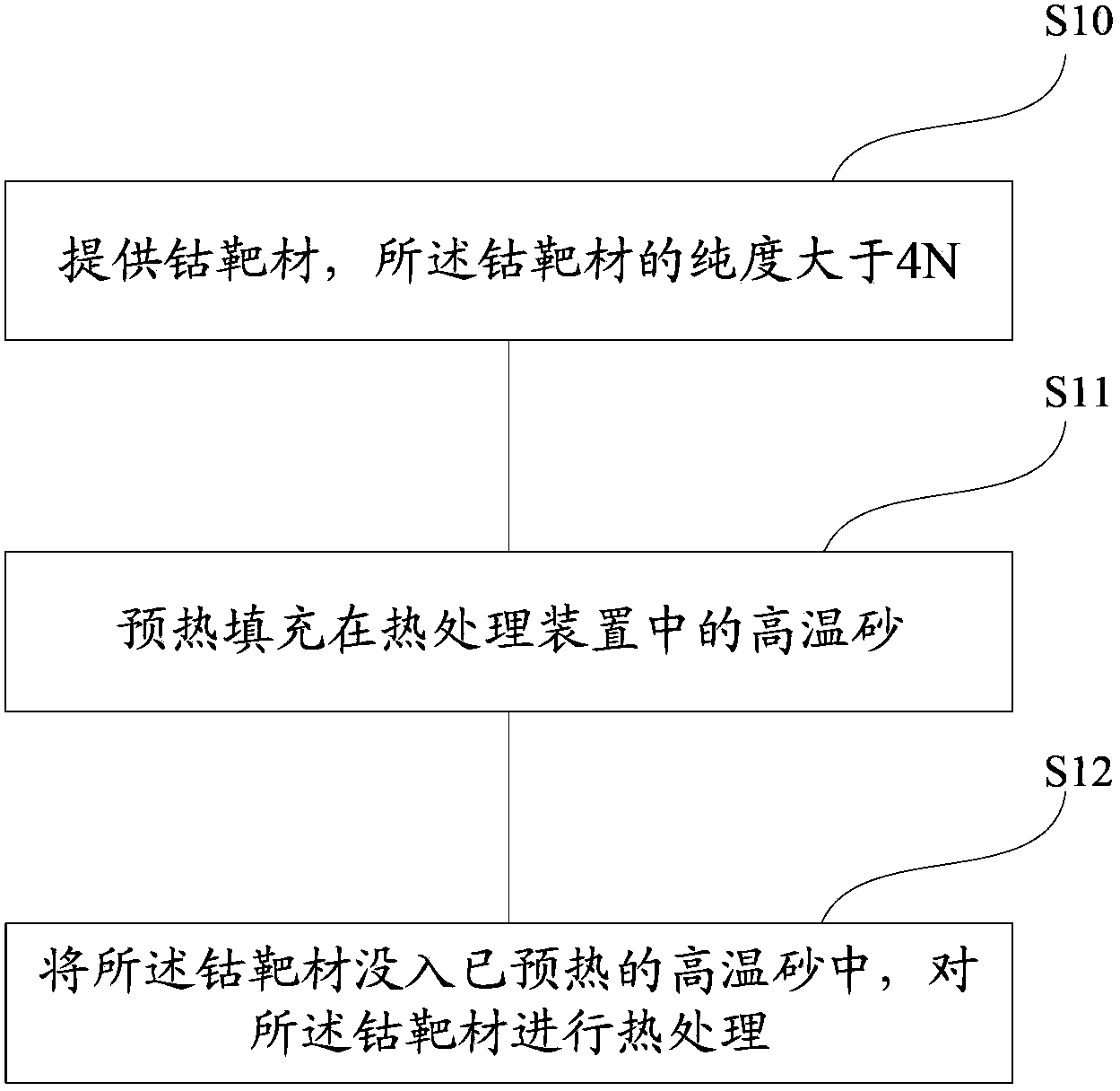
[0026] In an embodiment of the present invention, a cobalt target heat treatment method is provided, such as figure 1 shown, including steps:

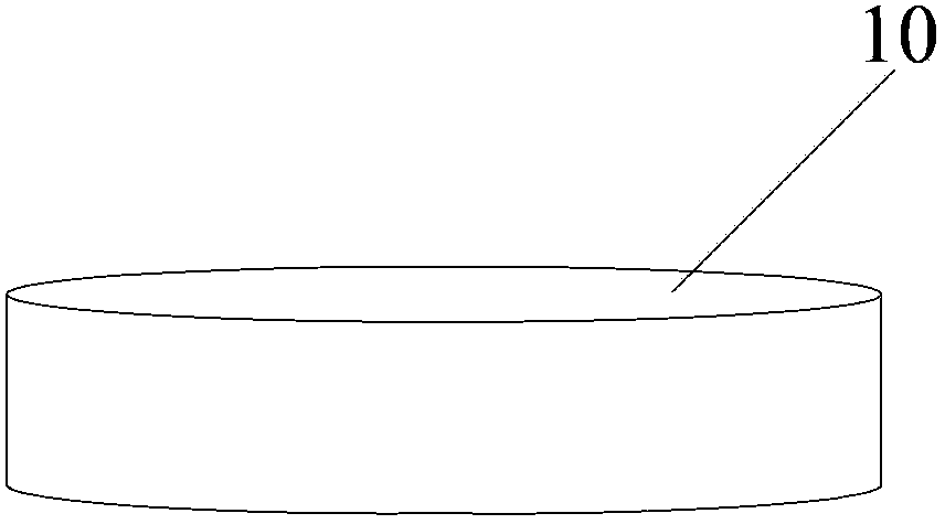
[0027] S10, providing a cobalt target material, the purity of the cobalt target material is greater than 4N;

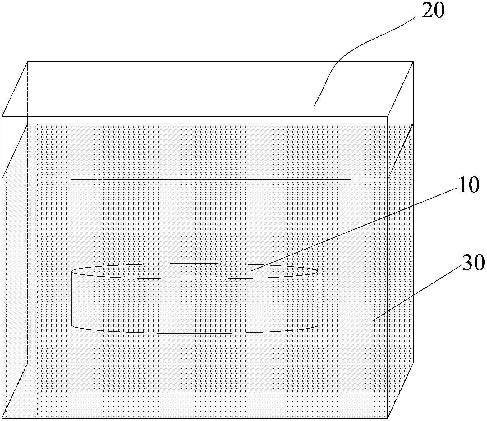
[0028] S11, preheating the sand filled in the heat treatment device;

[0029] S12, immersing the cobalt target material into the preheated sand, and performing heat treatmen...


PUM

PropertyMeasurementUnit
particle sizeaaaaaaaaaa

Abstract

The invention provides a heat treatment method of a cobalt target. The heat treatment method comprises the following steps of providing the cobalt target having the purity greater than 4 N; preheating sand; covering the cobalt target with the preheated sand; and performing heat treatment on the cobalt target. Compared with the prior art, the heat treatment method provided by the invention avoids the problems that the cobalt target obtained after the heat treatment process in the prior art does not have the desired magnetic conductivity and the crystalline grains of the cobalt target do not meet the requirements of sputtering in the prior art in the heating way of preheating sand bath.

Description

technical field [0001] The invention relates to the field of semiconductor manufacturing, in particular to a cobalt target heat treatment method. Background technique [0002] Cobalt targets are widely used in semiconductor integrated circuits. For example, metal silicide can be formed with silicon on the source, drain and gate of MOS transistors to reduce contact resistance. The above process is generally completed in the sputtering chamber. The specific process is as follows: first, an inert gas, such as argon, is introduced into the reaction chamber; the cobalt target is used as the cathode and connected to the negative electrode of the DC power supply. When the applied voltage reaches a certain value, the gas ionizes to generate positive ions to bombard the cathode, and the cobalt ions are Sputtering off the target surface. In the above process, in order to deposit cobalt ions on the silicon surface with directional movement, a permanent magnet is set on the surface of...

Claims


Application Information

Patent Timeline
Patent Type & Authority Applications(China)
IPC IPC(8): C22F1/10
Inventor 姚力军相原俊夫大岩一彦潘杰王学泽陈勇军
Owner KONFOONG MATERIALS INTERNATIONAL CO LTD
Why Eureka
Try Eureka