
Wide Spectrum Weak Pulse Laser Energy Measurement System

A pulsed laser and energy measurement technology, applied in the direction of instruments, etc., can solve the problems that the measurement band does not meet the short-wave band of X-rays, does not cover the measurement range, and is not applicable to weak signal occasions, etc., and achieves light weight, wide response wavelength range, and volume small effect

Active Publication Date: 2016-09-21
HANGZHOU INSTITUTE OF OPTICS AND FINE MECHANICS
View PDF4 Cites 0 Cited by
  • Summary
  • Abstract
  • Description
  • Claims
  • Application Information

AI Technical Summary

Problems solved by technology

[0010] First of all, the currently known invention (see patent CN200510105535.6, Sun Zhixu) measures the energy as mJ (mJ, 10 -3 Joule) level, not suitable for weak signal occasions
[0011] Secondly, the currently known invention (see patent CN200910089555.7, Peng Zhong) can measure weak energy, and the measurement accuracy can reach 2.2fJ / cm 2 ~5*105fJ / cm 2 However, the laser energy meter is firstly used outdoors, not for use in a vacuum cavity. Secondly, the energy meter is mainly used in the fields of laser guidance and laser ranging. To enable the laser signal to transmit long distances in the air, generally use The infrared band, that is to say, the measurement band does not meet the requirements of the X-ray short band
[0012] Thirdly, the currently known invention (see patent CN200410040820.X, Zhang Pengxiang) is mainly characterized by a wide spectral range, pulse type, and fast-response energy meter, but it is known from the patent document that the measurement band of this product is 0.19-11 microns, and there is no Covers the required measurement range of 121nm to 1nm

Method used


Image

  • Wide Spectrum Weak Pulse Laser Energy Measurement System
  • Wide Spectrum Weak Pulse Laser Energy Measurement System
  • Wide Spectrum Weak Pulse Laser Energy Measurement System

Examples


Embodiment Construction

[0037] The present invention will be further described below in conjunction with the accompanying drawings, but the protection scope of the present invention should not be limited accordingly.

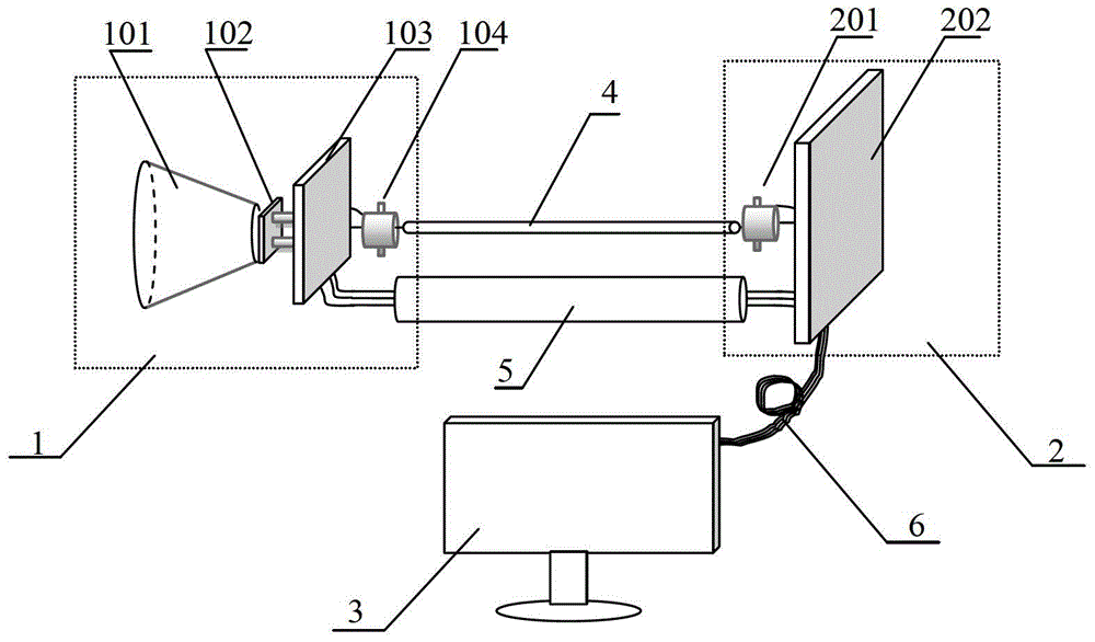
[0038] Please see first figure 1 , figure 1 It is a schematic diagram of the device structure of the wide-spectrum weak pulse laser energy measurement system of the present invention. It can be seen from the figure that the wide-spectrum weak pulse laser energy measurement system of the present invention is composed of a measurement system probe 1, a back-end signal amplification module 2 and a data acquisition card and The computer 3 of Labview software is composed of, the measurement system probe 1 and the back-end signal amplification module 2 are connected by a coaxial signal transmission line 4 and a control line 5, and the back-end signal amplification module 2 and the computer 3 They are connected by data acquisition cable 6.

[0039] The measuring system probe 1 includes a fu...


PUM


Abstract

A wide-spectrum weak pulse laser energy measurement system is characterized in that the system is composed of a measurement system probe, a back-end signal amplification module and a computer with a data acquisition card and Labview software, and the measurement system probe and the back-end signal amplification module They are connected by a coaxial signal transmission line and a control line, and the back-end signal amplification module is connected with the computer by a data acquisition cable. The present invention adopts the scheme of separating the pre-amplification and the post-amplification, the pre-amplification has the function of automatic shifting, and the post-amplification has the function of automatically switching the magnification. The invention has a wide range of response wavelengths, the short wavelength end has been extended to the X-ray band, the lowest energy detection capability of the invention can reach 10pJ, and the probe of the invention is small in volume and light in weight. The invention has important use value in the field of short-wavelength weak energy measurement, such as the field of harmonic pulse energy measurement in high-order harmonic experiments.

Description

technical field [0001] The invention relates to pulse laser energy measurement, in particular to a wide-spectrum weak pulse laser energy measurement system. Background technique [0002] Higher harmonic technology is the synthesis of individual attoseconds (10 -18 second) level ultrashort pulse and the main experimental method for generating X-rays in the water window band, because a single attosecond level ultrashort pulse can be used to study the movement of electrons in atoms or molecules, and X-rays in the water window band can be used in biological imaging It plays an extremely important role, so the research on high-order harmonic technology is very popular in today's world. [0003] The higher harmonic experiment involves the measurement of harmonic signals. The current general practice is to measure by X-ray CCD (charge coupled device) or MCP (micro channel plate). But the two have a shortcoming, the signal strength obtained is only the relative strength between th...

Claims


Application Information

Patent Timeline
Patent Type & Authority Patents(China)
IPC IPC(8): G01J11/00
Inventor 刁寒虎曾志男郑颖辉李儒新
Owner HANGZHOU INSTITUTE OF OPTICS AND FINE MECHANICS
Learn More