

Optical fiber micro-displacement air pressure detecting device
An air pressure measurement device and micro-displacement technology, which is applied to measurement devices, optical devices, fluid pressure measurement using optical methods, etc., can solve the problems of increasing the cost and achieve the effects of convenient processing, simple operation, and saving manpower and material resources
- Summary
- Abstract
- Description
- Claims
- Application Information
AI Technical Summary
Problems solved by technology
Method used
Image


Examples
Embodiment
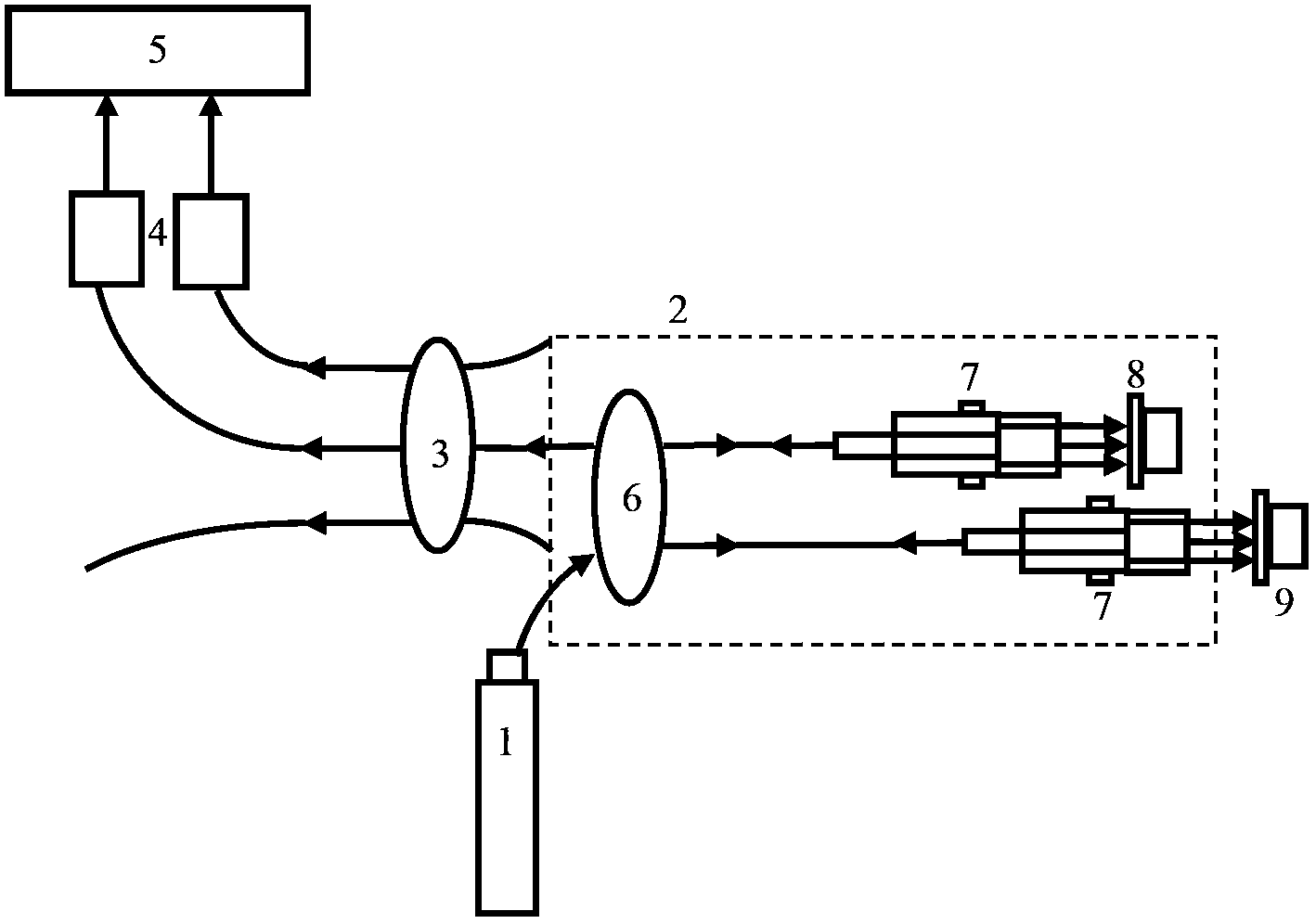
[0036] according to figure 1 The structure diagram of the preliminary experimental verification device construction, such as Figure 6 shown. The light emitted by the 1550nm (±3nm, power 2-5mw) narrow-band light source 1 passes through the 2×2 coupling device 6 and then enters the optical fiber micro-displacement sensor. The output end face of the straightener 7 is emitted, and part of it is reflected back into the original optical fiber through a reference angle cone diaphragm 8 to become the reference light, and the other part is reflected back into the original fiber through the angle cone diaphragm 9 to be measured, which is the light to be measured. Light; the two light beams have an optical path difference due to the difference in arm length, and interference occurs in the fiber coupler 6. After the interference signal passes through a 3×3 coupler 3, two beams of light waves with two fixed phase differences are selected to pass through the photoelectric Converter 4 is ...
PUM
 Abstract
Description
Claims
Application Information