A post-test simulation method for transformer internal fault identification based on coupled inductor port characteristics
A technology of internal faults and port characteristics, applied to electrical components, emergency protection circuit devices, etc., can solve problems such as numerical vibration, complex parameter identification methods, etc.
- Summary
- Abstract
- Description
- Claims
- Application Information
AI Technical Summary
Problems solved by technology
Method used
Image
Examples
Embodiment approach 1
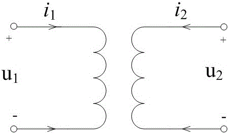
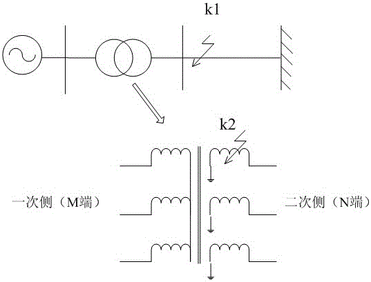
[0077] Implementation Mode 1: The structural diagram of a 38.5 / 525kV double-winding three-phase step-up transformer is as follows figure 1 , the transformer parameters are as follows: the three-phase transformer is connected by three single-phase transformers, the transformer ratio is 38.5 kV / 525 kV, the leakage inductance on both sides is 0.524mH, the winding resistance is ignored, and the sampling frequency is 20 kHz. A single-phase ground fault occurs at the transformer secondary side bus outlet (such as figure 2 Middle k1 point), the transition resistance is 50Ω.
[0078] (1) In the time window of 5ms, measure the voltage u of the primary side outlet terminal and the secondary side outlet terminal of the transformer respectively 1 , u 2 and current i 1 i 2 , using the equivalent circuit under normal operating conditions of the transformer to calculate the analog voltage
[0079] (1)
[0080] Then compare the measured voltage u at the outlet of the secondary si...
Embodiment approach 2
[0082] Implementation Mode 2: The structural diagram of a 38.5 / 525kV double-winding three-phase step-up transformer is as follows figure 1 , the transformer parameters are the same as in Example 1.
[0083] A single-phase ground fault occurs in the secondary side winding of the transformer (such as figure 2 Middle k2 point), the transition resistance is 50Ω.
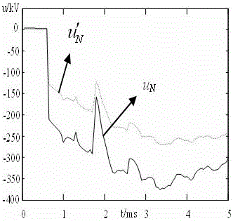
[0084] After a fault occurs in the power transmission system, the voltage at the outlet of the secondary side of the transformer is simulated and calculated according to the same method as in Example 1 , and then compare it with the measured voltage The degree of similarity of the waveforms (eg Figure 4 ), calculate the analog voltage and measured voltage The correlation coefficient of the waveform r = -0.6028 <0, so it is judged as a fault in the transformer area.
PUM
 Abstract
Description
Claims
Application Information
 - R&D
- Intellectual Property
- Life Sciences
- Materials
- Tech Scout
- Unparalleled Data Quality
- Higher Quality Content
- 60% Fewer Hallucinations
Browse by: Latest US Patents, China's latest patents, Technical Efficacy Thesaurus, Application Domain, Technology Topic, Popular Technical Reports.
© 2025 PatSnap. All rights reserved.Legal|Privacy policy|Modern Slavery Act Transparency Statement|Sitemap|About US| Contact US: help@patsnap.com


