Optical fiber acoustic sensor and optical fiber acoustic detection method

An acoustic wave sensor, fiber grating technology, applied in the measurement of ultrasonic/sonic/infrasonic waves, instruments, measuring devices, etc., can solve the problems of high cost, low sensitivity, complex structure, etc., and achieve the effect of high cost, high sensitivity, and improved sensitivity

Active Publication Date: 2013-12-25
武汉光谷光联网科技有限公司
View PDF0 Cites 14 Cited by
  • Summary
  • Abstract
  • Description
  • Claims
  • Application Information

AI Technical Summary

Problems solved by technology

[0008] In view of the above defects or improvement needs of the prior art, the present invention provides a fiber optic acoustic wave sensor and a fiber optic acoustic wave detection m

Method used


Image

  • Optical fiber acoustic sensor and optical fiber acoustic detection method
  • Optical fiber acoustic sensor and optical fiber acoustic detection method
  • Optical fiber acoustic sensor and optical fiber acoustic detection method

Examples


Embodiment 1

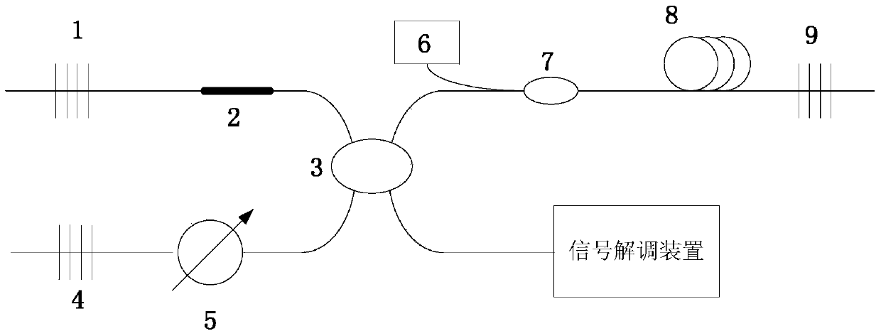
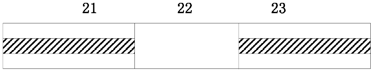
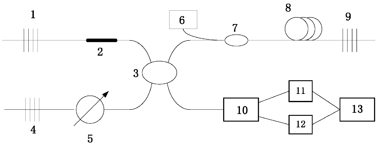
[0048] Such as image 3 As shown, the fiber optic acoustic wave sensor of this embodiment includes a first fiber grating 1 for wavelength selection; a sensing unit 2 for capturing weak acoustic signals; a coupler 3 with a power splitting ratio of 1:1, which is a transmission and the passive device for distributing signals, which have 4 ports; the second fiber grating 4 whose reflection wavelength is different from that of the first fiber grating 1 is used for wavelength selection; the tunable attenuator 5 can produce certain energy attenuation for the signal, and balance The loss of the two channels; the pump source 6 provides an excitation source for the laser; the wavelength division multiplexer 7 couples the pump light energy into the gain fiber; the gain fiber 8 provides gain for the laser; A fiber grating 1 and a second fiber grating 4 constitute the resonant cavity of the laser; a tunable optical filter 10 is used to filter out laser wavelengths; a first optical probe 11...

Embodiment 2

[0052] Such as image 3 As shown, the fiber optic acoustic wave sensor of this embodiment includes a first fiber grating 1 for wavelength selection; a sensing unit 2 for capturing weak acoustic signals; a coupler 3 with a power splitting ratio of 1:1, which is a transmission and the passive device for distributing signals, which have 4 ports; the second fiber grating 4 whose reflection wavelength is different from that of the first fiber grating 1 is used for wavelength selection; the tunable attenuator 5 can produce certain energy attenuation for the signal, and balance The loss of the two channels; the pump source 6 provides an excitation source for the laser; the wavelength division multiplexer 7 couples the pump light energy into the gain fiber; the gain fiber 8 provides gain for the laser; A fiber grating 1 and a second fiber grating 4 constitute the resonant cavity of the laser; a tunable optical filter 10 is used to filter out laser wavelengths; a first optical probe 11...


PUM

PropertyMeasurementUnit
Core diameteraaaaaaaaaa
Cladding diameteraaaaaaaaaa
Diameteraaaaaaaaaa

Abstract

The invention discloses an optical fiber acoustic sensor and an optical fiber acoustic detection method. The optical fiber acoustic sensor comprises a first optical fiber grating, a sensing unit, a coupler, a second optical fiber grating, a tunable attenuator, a pumping source, a wavelength division multiplexer, gain optical fibers and a reflector. The coupler comprises four ports, wherein the first port is connected with the first optical fiber grating through the sensing unit, the second port is connected with the second optical fiber grating through the tunable attenuator, the third port is connected with reflector through the wavelength division multiplexer and the gain optical fibers, the pumping source is connected with the wavelength division multiplexer, and the fourth port is connected with an external signal demodulation device. The dual laser gain competitive effect and the two-channel difference signal processing method are utilized to lower noise and improve flexibility. The optical fiber acoustic sensor has the advantages of being high in flexibility, simple in structure, firm, low in cost, high product success rate, stable in work, not flexible to environment temperature, an the like.

Description

technical field [0001] The invention belongs to the field of optical fiber acoustic wave sensors, and more specifically relates to an optical fiber acoustic wave sensor and a fiber optic acoustic wave detection method. Background technique [0002] The basic working principle of the optical fiber sensor is to send light into the modulator through the optical fiber, so that after the parameter to be measured interacts with the light entering the modulation area, the optical properties of the light (such as the intensity, wavelength, frequency, phase, and normal state of the light) etc.) changes, which is called the modulated signal light, which is sent to the photodetector through the optical fiber, and after demodulation, the measured parameters are obtained. Optical fiber sensors can be used to measure a variety of physical quantities, such as sound field, electric field, pressure, temperature, angular velocity, acceleration, etc., and can also complete measurement tasks th...

Claims


Application Information

Patent Timeline
IPC IPC(8): G01H9/00
Inventor 鲁平田铭张亮刘德明
Owner 武汉光谷光联网科技有限公司
Why Eureka
Try Eureka