Hollow optical slip ring and optical signal transmission method thereof

A smooth ring and hollow technology, applied in the field of smooth rings, can solve the problems of high precision requirements, low connection efficiency, high cost, etc., and achieve the effect of low precision requirements, simple structure, and easy realization

Active Publication Date: 2013-12-25
8TH RES INST OF CETC
View PDF9 Cites 7 Cited by
  • Summary
  • Abstract
  • Description
  • Claims
  • Application Information

AI Technical Summary

Problems solved by technology

The lower surface of the transmission medium is a tapered surface. These optical fiber rotary connectors have high requirements on

Method used


Image

  • Hollow optical slip ring and optical signal transmission method thereof
  • Hollow optical slip ring and optical signal transmission method thereof

Examples


Embodiment Construction

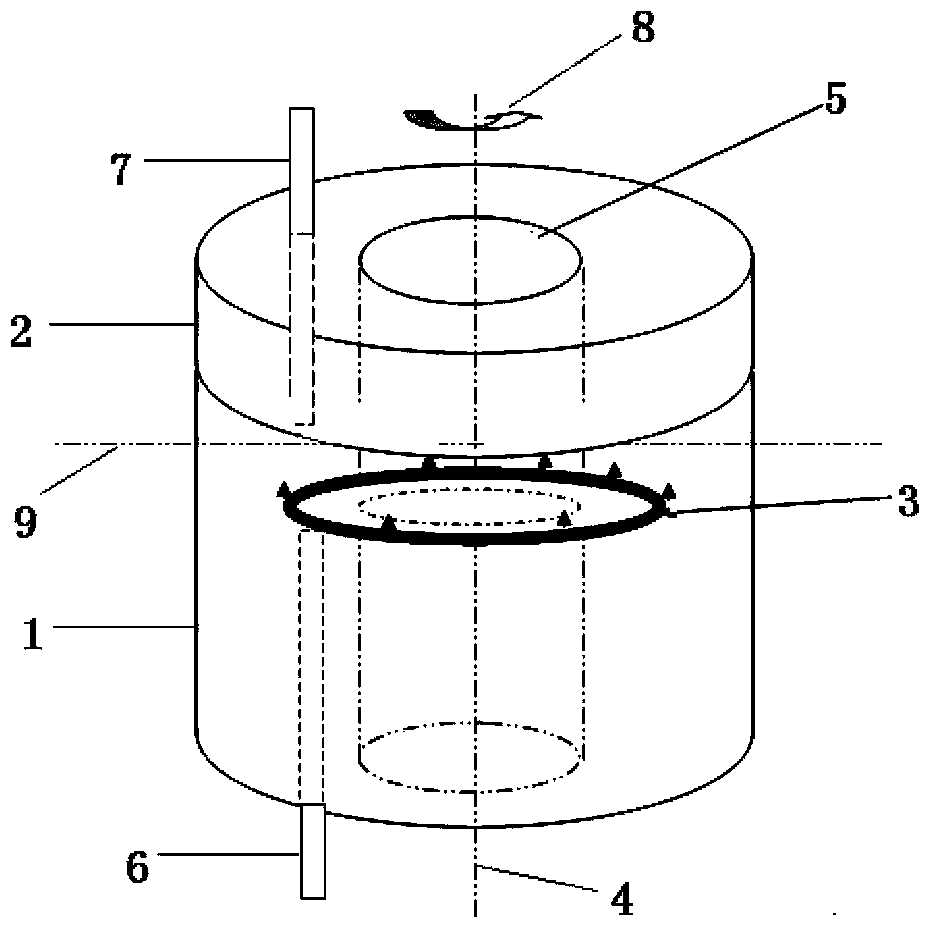
[0017] like figure 1 As shown, the hollow smooth ring provided by the present invention includes a stator 1, a rotor 2, an input fiber channel 6, an inclined fiber grating 3, and an output fiber channel 7.

[0018] The stator 1 and the rotor 2 are composed of an annular base body, the radial outer circle and the radial inner circle of the stator 1 and the rotor 2 are equal, and the axes 4 coincide with each other to form a hollow structure. The opposite surface of the annular base of the stator and the rotor is a plane, which is called the upper surface 9 of the stator.

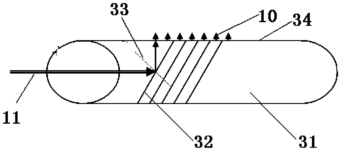
[0019] Slanted fiber grating 3 forms a ring-shaped tubular structure, partly arranged in the stator, the center line of the ring-shaped tilted fiber grating 3 coincides with the stator axis 4, and the center plane of the ring-shaped tilted fiber grating 3 is the center line of the ring-shaped tilted fiber grating 3 Vertically and intercepting the plane with the largest area of ​​the annular inclined fiber gr...


PUM


Abstract

A hollow optical slip ring comprises a stator, a rotor, an input optical fiber channel, an annular inclined optical fiber grating, and an output optical fiber channel. Both the stator and the rotor are composed of annular base bodies, the annular radial outer circles the stator and the rotor are the same, the annular radial inner circles of the stator and the rotor are the same, the axis of the stator and the axis of the rotor coincide with each other, and a hollow structure is formed. A part of the inclined optical fiber grating is arranged in the stator, a full-grating area is engraved on the circumference of the inclined optical fiber grating, when light beams in the input optical fiber channel is shot to the inclined optical fiber grating, the inclined optical fiber grating which is designed with a certain gradient can reflect a part of the input light beams, and reflected light passes optical fibers with a wrapping layer peeled, then is vertically transmitted upwards and enters the output optical fiber channel. The hollow optical slip ring is simple in structure and easy to achieve, the requirement for precision of a mechanical device is not high, and gases, liquids and other flow media can be transmitted in a hollow state.

Description

technical field [0001] The invention relates to a smooth ring, in particular to a rotating smooth ring. Background technique [0002] Some characteristics of optical fiber, such as wide bandwidth, anti-interference, low loss, light weight, and small size, make it an ideal signal carrier in more and more applications. In the types of optical fiber signal transmission, in some cases, the transmission of optical signals often requires a rotating coupling device in an intermediate link of the line, such as between the radar antenna and its on-board signal processing system, between the submarine robot and the control ship, The connection lines between the manipulator and the main console used in industry, etc., all need to realize the connection of the optical fiber optical path in two relatively rotating parts. The ordinary fixed connector cannot complete the dynamic connection, and the smooth ring (also known as the optical fiber rotary connection) Device) is an indispensable...

Claims


Application Information

Patent Timeline
IPC IPC(8): G02B6/34G02B6/36
Inventor 陆兆辉
Owner 8TH RES INST OF CETC
Why Eureka
Try Eureka