Coupling inductor and voltage doubling circuit combined set-up converter

A technology of boost converter and coupled inductor, applied in the field of boost converter, can solve the problems of large switching loss, instantaneous current impact, complex structure, etc., and achieve the effect of reducing loss and voltage spike.

Inactive Publication Date: 2013-12-25
王琳
View PDF6 Cites 14 Cited by
  • Summary
  • Abstract
  • Description
  • Claims
  • Application Information

AI Technical Summary

Problems solved by technology

However, the output voltage gain of the conventional BOOST or two-phase interleaved parallel BOOST converter is small, the voltage stress of the power switch is large, and the switching loss is large
For this reason, the method of using soft switching circuit has appeared one after another. Although the soft switching of the power switching tube can be realized, the voltage stress of the power switching tube cannot be reduced; Voltage requires a large number of switched capacitors, and the structure is complex

Method used


Image

  • Coupling inductor and voltage doubling circuit combined set-up converter

Examples


Embodiment Construction

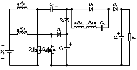
[0009] The present invention is a boost converter that combines a coupled inductor and a voltage doubler circuit. Such as figure 1 As shown, it includes two controllable power switch tubes ( Q 1 , Q 2 ), one with two windings ( N p1 , N s1 ) of coupled inductors, one with two windings ( N p2 , N s2 ) coupled inductor, three unidirectional rectifier diodes ( D 1 , D 2 , D 3 ), an output diode ( D o ), a clamp capacitor ( C 1 ), two intermediate storage capacitors ( C 2 , C 3 ), an output filter capacitor ( C o ). The specific connection method is as follows: a winding of the first coupled inductor ( N p1 ) and a winding of the second coupled inductor ( N p2 ) terminal with the same name and DC input power supply ( V in ) is connected to the positive pole, and one winding of the first coupled inductor ( N p1 ) and the other end of the power switch tube ( Q 1 ) drain and intermediate energy storage capacitor ( C 2 ) connected to the negati...


PUM


Abstract

The invention discloses a topological structure of a coupling inductor and voltage doubling circuit combined set-up converter, and belongs to the power electronic technical field. The coupling inductor and voltage doubling circuit combined set-up converter has the high set-up capacity and comprises two controllable power switch tubes, two coupling inductors with two windings, three one-way rectifier diodes, an output diode, a clamping capacitor, two middle energy-storage capacitors and an output filtering capacitor. Output with the high set-up ratio can be achieved through the coupling inductors and a voltage doubling circuit in the coupling inductor and voltage doubling circuit combined set-up converter, the peak voltage stress of the power switch tubes and the diodes can be reduced, meanwhile, zero-current turn-on of the power switch tubes and turn-off of the diodes are achieved through leakage inductance of the coupling inductors, and the coupling inductor and voltage doubling circuit combined set-up converter is suitable for renewable energy electric generation systems such as a standby energy system, a photovoltaic cell and a fuel cell in future, and has the good practical value and the wide popularization prospects.

Description

technical field [0001] The invention relates to a DC-DC converter in the field of power electronics, in particular to a boost converter combining a coupling inductor and a voltage doubler circuit. Background technique [0002] In recent years, the technology of grid-connected power generation using clean and renewable energy such as solar energy and fuel cells has attracted more and more attention, and research on related application technologies has also increased. Due to the influence of environment, temperature and other factors, the output voltage of these renewable energy sources usually fluctuates greatly, and the voltage level of the monomer is low, while the grid-connected power generation system requires a DC bus with a higher voltage. However, the output voltage gain of the conventional BOOST or two-phase interleaved parallel BOOST converter is small, the voltage stress of the power switch is large, and the switching loss is large. For this reason, the method of u...

Claims


Application Information

Patent Timeline
Patent Type & Authority Applications(China)
IPC IPC(8): H02M3/06H02M1/14
Inventor 胡雪峰王琳
Owner 王琳
Why Eureka
Try Eureka