Novel LED constant-current drive circuit

A constant current drive and circuit technology, applied in the direction of electric lamp circuit layout, electric light source, lighting device, etc., can solve the problem of poor constant current effect of high-power LED lamp, poor constant current effect of resistance-capacity step-down driver, and constant current working voltage range. narrow and other problems, to achieve the effect of good constant current effect, wide constant current operating voltage range and low cost

Active Publication Date: 2015-05-13
中山市领航光电科技有限公司
View PDF8 Cites 0 Cited by
  • Summary
  • Abstract
  • Description
  • Claims
  • Application Information

AI Technical Summary

Problems solved by technology

Among them, the constant current effect of the IC constant current drive circuit is good, but the cost of the IC is high; the current RCC drive circuit is simple and low in cost, but the constant current effect for high-power LED lamps is poor, and it can only be used for low-power LED lamps. LED lamp drive; constant current diode driver has better constant current effect, but the constant current operating voltage range is narrow, and can only be used in a few places with small voltage fluctuations, and the scope of use is limited; RC step-down driver has poor constant current effect and belongs to range to be eliminated

Method used


Image

  • Novel LED constant-current drive circuit

Examples


Embodiment Construction

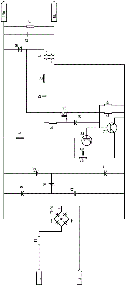
[0020] refer to figure 1 , a new type of LED constant current drive circuit provided by the present invention includes an AC input terminal, a rectification module, a filter module with a power factor correction function, a current amplification module and an output module connected in sequence. A metal oxide film fuse resistor F1 is arranged between the AC input terminal and the rectifier module. The rectification module is preferably a bridge rectification module. The filter module is composed of filter capacitors C1, C2 and one-way diodes D5 to D7, which play the role of filtering and improving the PFC value. The current amplifying module includes a current-limiting resistor R1 arranged between two poles, a first triode T2, and a second triode T3, and the first triode T2 and the second triode T3 are commonly used NPN transistors (PNP transistors can also be used), the output terminals of the current-limiting resistor R1, the first transistor T2, and the second transistor ...


PUM


Abstract

The invention discloses a novel LED constant-current drive circuit. The novel LED constant-current drive circuit comprises an alternating current input end, a rectifier module, a filtering module with the power factor correction function, a current amplifying module and an output module, wherein the alternating current input end, the rectifier module, the filtering module, the current amplifying module and the output module are connected with one another in sequence. The current amplifying module comprises a current-limiting resistor and two triodes, wherein the current-limiting resistor and the two diodes are sequentially connected between the two electrodes of the current amplifying module. A constant-current control module is further arranged on the drive circuit. The constant-current control module comprises a field-effect tube. A source electrode of the field-effect tube is connected with base electrodes of the two triodes. A control grid electrode of the field-effect tube is connected between the current-limiting resistor and the two triodes. The LED constant-current drive circuit has the function of automatically conducting feedback and control according to changes of an output current, the output current can be automatically adjusted through feedback and control, a current which is outputted to flow through an LED can be constant, the constant-current effect is good, the long service life of an LED lamp can be ensured, and the LED constant-current drive circuit is economical and good in use effect.

Description

technical field [0001] The invention relates to an LED constant current drive circuit, in particular to a novel LED constant current drive circuit for an LED lighting lamp. Background technique [0002] Existing LED constant current drive circuits mainly include four types: constant current drive circuits using ICs, RCC drive circuits, constant current diode drive circuits and resistance-capacitance step-down drive circuits. Among them, the constant current effect of the IC constant current drive circuit is good, but the cost of the IC is high; the current RCC drive circuit is simple and low in cost, but the constant current effect for high-power LED lamps is poor, and it can only be used for low-power LED lamps. LED lamp drive; constant current diode driver has better constant current effect, but the constant current operating voltage range is narrow, and can only be used in a few places with small voltage fluctuations, and the scope of use is limited; RC step-down driver h...

Claims


Application Information

Patent Timeline
Patent Type & Authority Patents(China)
IPC IPC(8): H05B37/02
Inventor 彭继辉
Owner 中山市领航光电科技有限公司
Why Eureka
Try Eureka