High velocity mist evaporation

An evaporation system and speed technology, applied in industrial evaporators and snowmaking machines, air conditioning, seawater desalination fields, to achieve the effect of improving fan efficiency

Inactive Publication Date: 2013-12-25
HIVAP
View PDF14 Cites 16 Cited by
  • Summary
  • Abstract
  • Description
  • Claims
  • Application Information

AI Technical Summary

Problems solved by technology

However, not all establishments accommodate evaporative coolers; sometimes building codes do not allow these for health purposes

Method used


Image

  • High velocity mist evaporation
  • High velocity mist evaporation
  • High velocity mist evaporation

Examples


Embodiment Construction

[0066] For convenience, the invention will be described hereinafter with specific reference to air conditioners, although the invention is equally applicable to industrial evaporation for seawater desalination, pharmaceuticals etc. and snowmaking machines, it should be understood that the invention is not limited thereto.

[0067] Although the invention is particularly applicable to air conditioning, and this description is focused on that application, the same invention can also be used as an evaporation front end for desalination or sewage treatment systems / processes, and in snowmaking machines, without the need for pumps to feed the nozzles. pressure.

[0068] First it is worth giving some general background on the concepts behind the invention.

[0069] A vortex disk is a highly efficient mechanical device that is essentially a wheel. Rotating the atomizing disc requires less energy than having to use a pump to pressurize the reverse osmosis (RO) components in a tradition...


PUM


Abstract

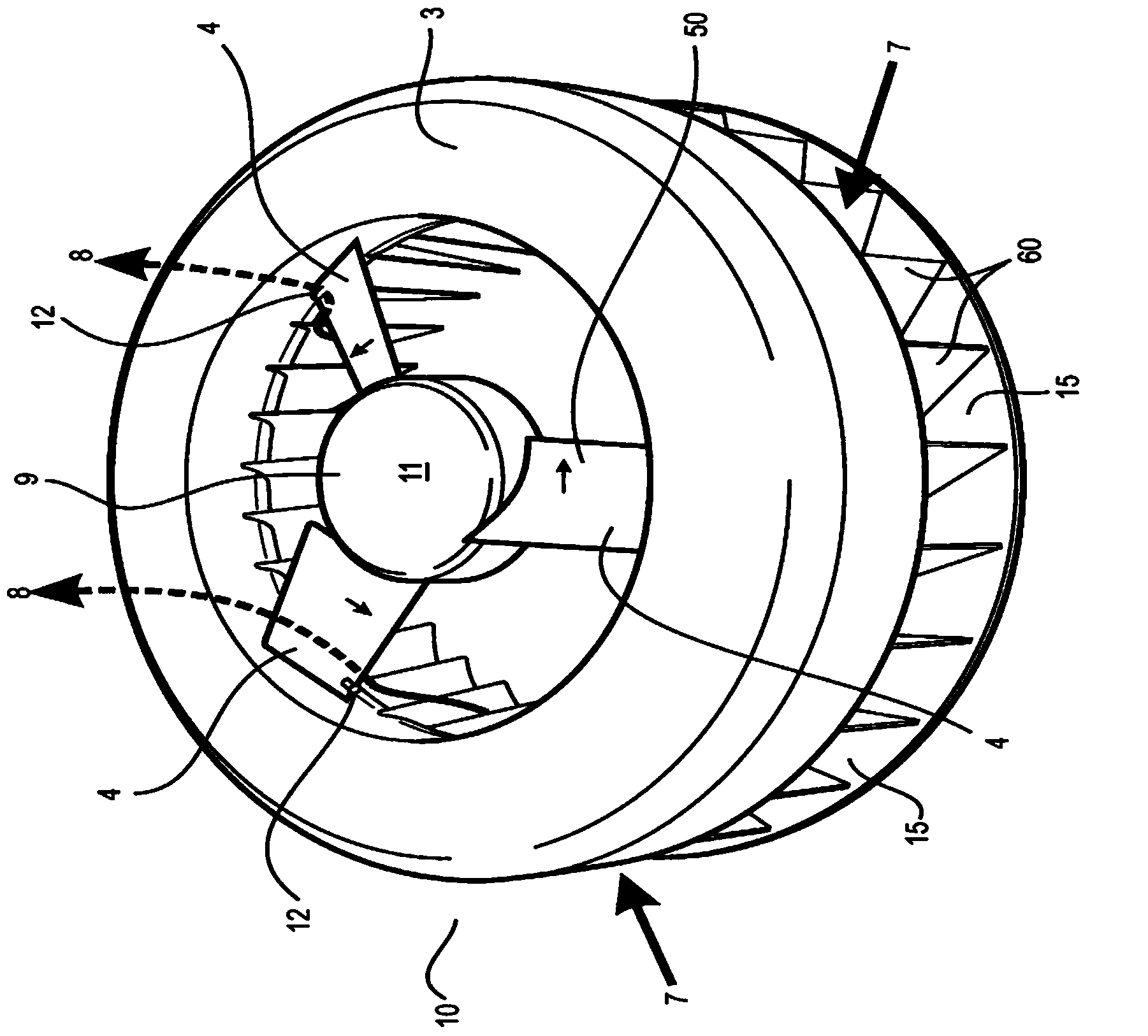
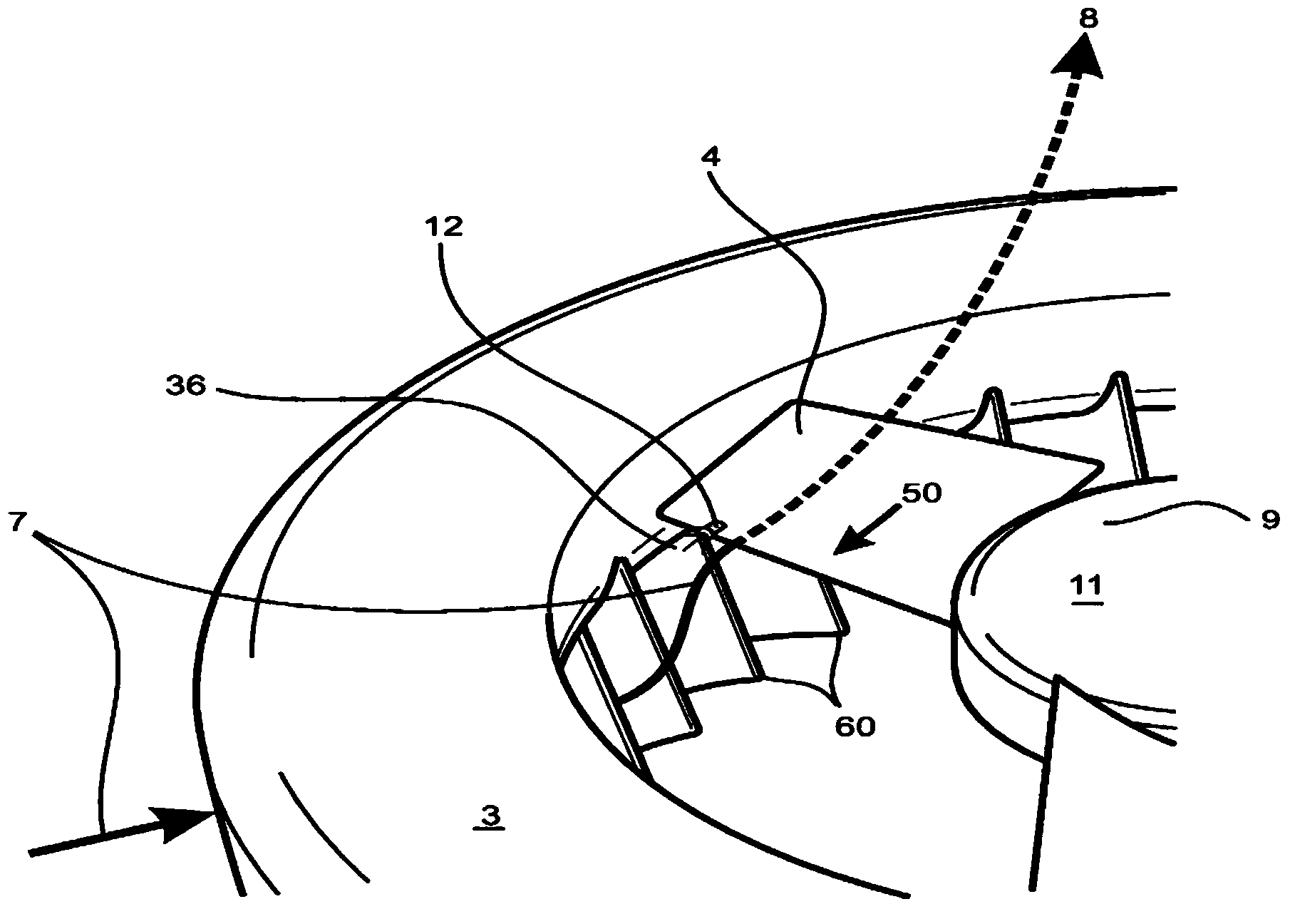
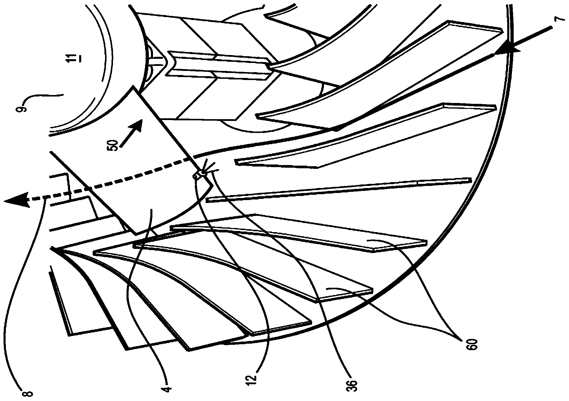
An evaporation system (10) and method has at least one fan (9) operatively connected to drive means (30) to effect fan rotation, at least one flow path to supply liquid to at least one nozzle (12) to spray a mist of the liquid under centrifugal pressure. Velocity differential between the rotating nozzle(s) and airflow created by the at least one fan provides evaporation of the sprayed liquid. Inlet vanes (60) direct airflow in a direction contra to fan rotation to increase velocity differential. The nozzles can be on fan blades (4) and / or a central disc / hub (2). The method and system can be used for air conditioning, snow making, desalination or in industrial or commercial evaporators.

Description

technical field [0001] The invention relates to an evaporation method, device and system using high-speed fog evaporation, especially suitable for air conditioning, seawater desalination, industrial evaporators and snowmaking machines. Background technique [0002] It is well known that evaporative air conditioners consume less energy and are more affordable than refrigeration air conditioners, but they do not perform well in humid environments. They cycle irreversibly; they only cool, not heat. Evaporative coolers are simple in construction and principle, consisting of a circulating fan, a wet pad and a pump mounted in a "cassette" system to provide coolant, usually water, to wet the pad in a reservoir. Since they have no compressor, they do not use coolants like CFC (Chlorofluorocarbons) and HCFCs (Hydrochlorofluorocarbons) in cooling methods. They rely solely on the evaporation of moisture from the broad surface area of ​​the wet pad to cool the air. Known techniques, ...

Claims


Application Information

Patent Timeline
Patent Type & Authority Applications(China)
IPC IPC(8): F24F5/00F24F6/16F28C3/08B05B3/02
CPCF24F5/0035F24F6/14F24F6/16F25C3/04F25C2303/046F25C2303/048Y02B30/54B01D47/08B05B3/022B05B3/0427B05B3/06F24F2006/146
Inventor G·S·阿蒂
Owner HIVAP
Why Eureka
Try Eureka