crank processing technology
A processing technology and crank technology, applied in the field of crank processing technology, can solve the problems of low processing efficiency, weak crank bearing capacity, complicated crank processing technology, etc., and achieve the effects of improving productivity, enhancing bearing capacity and strength, and rationally arranging
- Summary
- Abstract
- Description
- Claims
- Application Information
AI Technical Summary
Problems solved by technology
Method used
Image
Examples
Embodiment 1
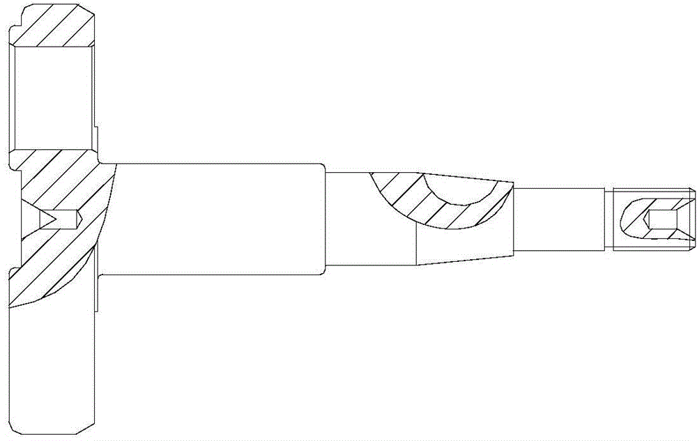
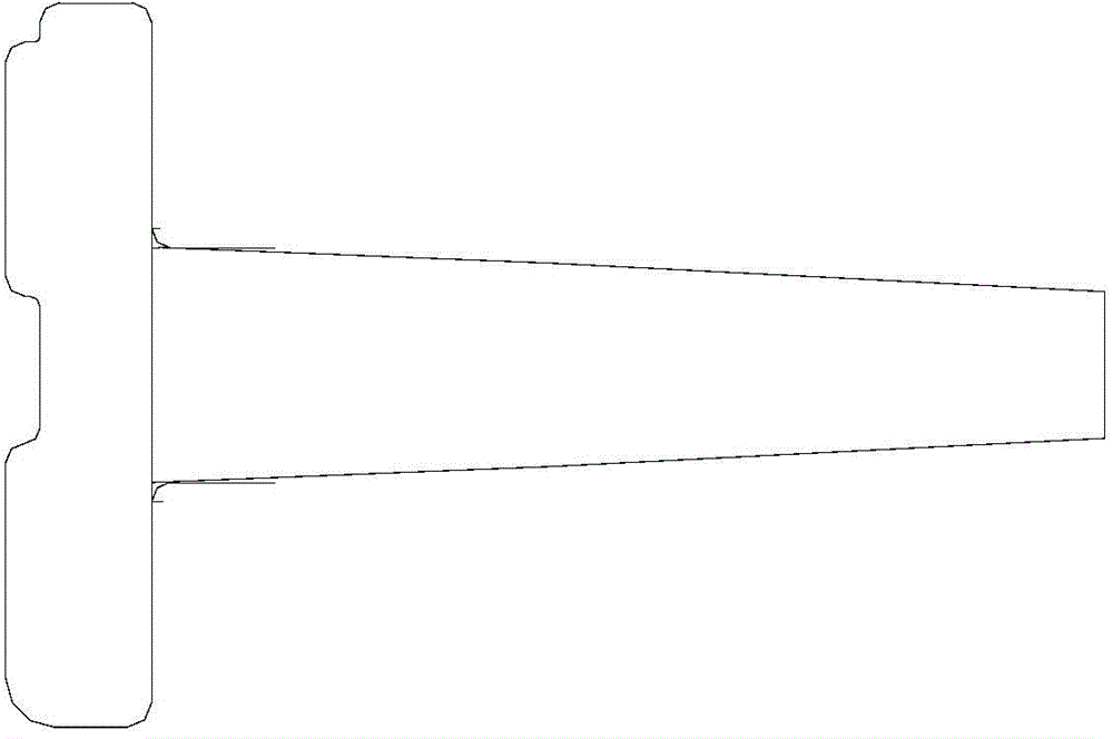
[0017] see figure 1 with figure 2 , a crank processing technology, comprising the following steps,
[0018] (1) Blank processing stage: prepare the crank blank, which is 20Cr steel, with a hardness HRC value of 20°, place the forged crank blank on a flat end face milling machine, and process the blank to the specified size; The surface of the workpiece is used as the positioning reference, and the center hole is drilled at the geometric center of the two ends of the crank with a bench drill;
[0019] (2) Rough machining stage: take the center holes on the two ends of the crank as the positioning reference, and use a CNC lathe to perform rough and fine turning and drilling and eccentric machining on the crank shaft and big end respectively; install a semicircular key on the milling and drilling machine The milling cutter processes the keyway on the shaft, and the thread rolling machine is used to process the shaft, and the processed workpiece is heat treated. The hardness of...
Embodiment 2
[0022] see figure 1 with figure 2 , a crank processing technology, comprising the following steps,
[0023] (1) Blank processing stage: prepare the crank blank, which is 20Cr steel, with a hardness HRC value of 23°, place the forged crank blank on a flat end face milling machine, and process the blank to the specified size; The surface of the workpiece is used as the positioning reference, and the center hole is drilled at the geometric center of the two ends of the crank with a bench drill;
[0024] (2) Rough machining stage: take the center holes on the two ends of the crank as the positioning reference, and use a CNC lathe to perform rough and fine turning and drilling and eccentric machining on the crank shaft and big end respectively; install a semicircular key on the milling and drilling machine The milling cutter processes the keyway on the shaft, and the thread rolling machine is used to process the shaft, and the processed workpiece is subjected to heat treatment. ...
Embodiment 3
[0027] see figure 1 with figure 2 , a crank processing technology, comprising the following steps,
[0028] (1) Blank processing stage: prepare the crank blank, which is 20Cr steel, with a hardness HRC value of 25°, place the forged crank blank on a flat end face milling machine, and process the blank to the specified size; The surface of the workpiece is used as the positioning reference, and the center hole is drilled at the geometric center of the two ends of the crank with a bench drill;
[0029] (2) Rough machining stage: take the center holes on the two ends of the crank as the positioning reference, and use a CNC lathe to perform rough and fine turning and drilling and eccentric machining on the crank shaft and big end respectively; install a semicircular key on the milling and drilling machine The milling cutter processes the keyway on the shaft, and the thread rolling machine is used to process the shaft, and the processed workpiece is heat-treated. The hardness HR...
PUM
| Property | Measurement | Unit |
|---|---|---|
| hardness | aaaaa | aaaaa |
| hardness | aaaaa | aaaaa |
| hardness | aaaaa | aaaaa |
Abstract
Description
Claims
Application Information
 - R&D
- Intellectual Property
- Life Sciences
- Materials
- Tech Scout
- Unparalleled Data Quality
- Higher Quality Content
- 60% Fewer Hallucinations
Browse by: Latest US Patents, China's latest patents, Technical Efficacy Thesaurus, Application Domain, Technology Topic, Popular Technical Reports.
© 2025 PatSnap. All rights reserved.Legal|Privacy policy|Modern Slavery Act Transparency Statement|Sitemap|About US| Contact US: help@patsnap.com


