Light beam orbital angular momentum generating device

An orbital angular momentum and generating device technology, applied in the field of optical communication, can solve problems such as high cost and complex optical path, and achieve the effect of reducing the number of use

Active Publication Date: 2014-01-01
WUHAN POST & TELECOMM RES INST CO LTD
View PDF6 Cites 10 Cited by
  • Summary
  • Abstract
  • Description
  • Claims
  • Application Information

AI Technical Summary

Problems solved by technology

[0003] However, in practical applications, when multiple beams of light are made to generate different helical phases, it is necessary to use a silicon-based liquid crystal for each beam to generate a corresponding optical orbital angular momentum for each beam, resulting in high cost, and at the same time, the optical path is also complicated. relatively complex

Method used


Image

  • Light beam orbital angular momentum generating device
  • Light beam orbital angular momentum generating device
  • Light beam orbital angular momentum generating device

Examples


Embodiment Construction

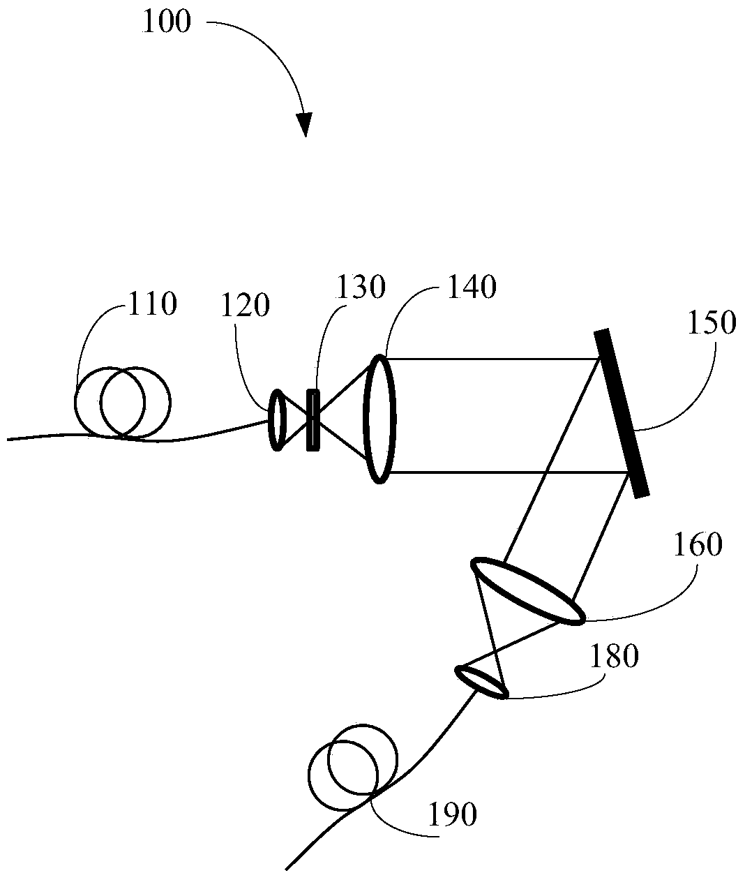
[0021] see figure 1 , a light beam orbital angular momentum generating device 100 provided in this embodiment is used to generate corresponding angular momentum for at least one beam of light. In this embodiment, the light beam is generated by an optical fiber assembly 110 . The beam orbital angular momentum generating device 100 includes a first lens 120 , a second lens 140 , a liquid crystal on silicon 150 , a third lens 160 and a fourth lens 180 . The first lens 120 and the second lens 140 are sequentially arranged and combined to form a telephoto system, and the third lens 160 and the fourth lens 180 are sequentially combined to form a lens system. The liquid crystal on silicon 150 is located between the second lens 140 and the third lens 160 .

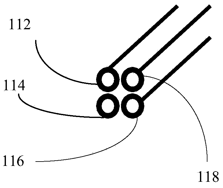
[0022] Please combine figure 2 , in this embodiment, the optical fiber assembly 110 includes four optical fibers, namely an optical fiber 112 , an optical fiber 114 , an optical fiber 116 and an optical fiber 118 . Optical fi...


PUM


Abstract

The invention provides a light beam orbital angular momentum generating device which is used for generating corresponding angular momentum to at least one light beam. The light beam orbital angular momentum generating device comprises a first lens, a second lens, silicon-based liquid crystal, a third lens and a fourth lens. A telescope system combined by the first lens and the second lens amplifies at least one light beam. The silicon-based liquid crystal is divided into multiple partitions, and the number of the partitions correspond to that of the light beams. The silicon-based liquid crystal allows the amplified light beams to generate orbital angular momentum corresponding to partition number. A telescope system combined by the third lens and the fourth lens sends out the light beams generating orbital angular momentum. The light beam orbital angular momentum generating device has the advantages that the silicon-based liquid crystal is divided into multiple partitions, the light beams respectively enter the partitions, the number of the partitions equals to that of the light beams, the phase of each partition is the spiral phase different in level, multiple light beams and multi-level spiral phases can be generated, and number of the silicon-based liquid crystal can be reduced effectively.

Description

technical field [0001] The invention relates to the field of optical communication, in particular to a device for generating beam orbital angular momentum. Background technique [0002] At present, the orbital angular momentum of a beam has important application value in the field of high-density information storage and transmission. The orbital angular momentum of a beam means that the beam has an angular momentum related to the angular phase distribution, and its phase is a spiral phase structure. A liquid crystal on silicon (LCOS) generates a helical phase for a beam of light. [0003] However, in practical applications, when making multiple beams of light produce different helical phases, it is necessary to use a silicon-based liquid crystal for each beam so that each beam of light generates a corresponding optical orbital angular momentum, resulting in high cost and the optical path. Relatively complex. Contents of the invention [0004] In view of this, the present...

Claims


Application Information

Patent Timeline
Patent Type & Authority Applications(China)
IPC IPC(8): G02F1/13
Inventor 邱英尤全谢德权李淼峰刘子晨
Owner WUHAN POST & TELECOMM RES INST CO LTD
Why Eureka
Try Eureka