Automatic feeding device of wheel body type workpiece machine tool

An automatic feeding and workpiece technology, applied in metal processing and other directions, can solve the problems of complex structure, high degree of automation and high risk, and achieve the effect of simple structure, high degree of automation and safe operation.

Inactive Publication Date: 2014-01-08
DANDONG DONGDA CONTROL EQUIP
View PDF8 Cites 6 Cited by
  • Summary
  • Abstract
  • Description
  • Claims
  • Application Information

AI Technical Summary

Problems solved by technology

[0002] At present, the methods of transferring relatively large workpieces to the processing position of the processing machine mainly include manual handling, balance crane lifting and other methods. These methods are used in processing occasions that do not require high continuous processing. Since the operator will directly contact the structural components inside the machine tool, including the rotating and clamping actions, there is a high risk, and the labor intensity of the operator is also high
[0003] Another method is a semi-automatic way of transporting the processed workpiece to the clamping position of the machine tool by means of motor drag, hydraulic or pneumatic drive. After processing, the workpiece will be automatically carried out or returned to the operating position, or transported to the remote material basket Among them, the machine tool automatically starts to drag or feed the conveying device of the processed workpiece during operation. The conveying device is controlled by the machine tool control system and cooperates with the continuous operation of the machine tool. The technical disadvantages are complex structure, relatively high cost, and the main application For the transfer of light-weight processed workpieces, such as Chinese patent: Patent No. 201120574373.1 provides an "automatic loading machine", which is only suitable for lightweight workpiece loading, not suitable for heavy-duty workpiece loading
Another Chinese patent: Patent No. 201120545520.2 The "heat treatment rack automatic loading wheel hub device" is suitable for large-volume and heavy processed work. It adopts a parallel jig arm structure, which has a complex structure and high cost
[0004] The other is a fully automatic manipulator operating device configured in an automated production line to transfer and place workpieces to be processed. It has a high degree of automation, but is expensive and has a more complicated mechanism. The processing machine tool and the transfer device cannot be separated, so it cannot be used in processing. Processing occasions where the machine tool is independent of the conveying device

Method used


Image

  • Automatic feeding device of wheel body type workpiece machine tool
  • Automatic feeding device of wheel body type workpiece machine tool
  • Automatic feeding device of wheel body type workpiece machine tool

Examples


Embodiment Construction

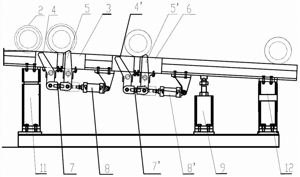
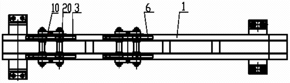
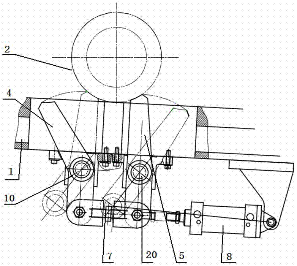
[0012] The automatic feeding device for wheel-type workpiece machine tools disclosed in the patent application of the present invention is a conveying and feeding device that can cooperate with various medium and large-volume wheel-type workpiece processing machine tools, such as wheel hub quenching processing machine tools. The wheel body type workpiece refers to a workpiece to be machined with a cylindrical outer surface, or a nearly cylindrical outer surface, or a circumferential outer surface.

[0013] The composition of the automatic feeding device of the wheel-type workpiece machine tool includes a conveying platform guide rail 1, the support part of the conveying platform guide rail 1 makes the conveying platform 1 in an inclined state, and the inclination angle of the conveying platform guide rail 1 enables the workpiece 2 to be processed on the conveying platform guide rail 1. It rolls and moves by itself, so that the workpiece 2 to be processed is sent step by step fr...


PUM


Abstract

The invention provides an automatic feeding device of a wheel body type workpiece machine tool. The automatic feeding device comprises a conveying platform guide rail and a supporting part of the conveying platform guide rail, the supporting part enables the conveying platform to be in a slant working state, a material loading station and a machining station are downwards arranged in the slant direction of the conveying platform guide rail, linkage control supports are arranged in the two stations, and each linkage control support is formed by a shifting rod set rotation middle shaft, a location rod set rotation middle shaft, a shifting rod, a location rod and a driving power part. According to the technical scheme, the structural arrangement of the conveying platform guide rail with a certain slant angle and the linkage control supports of the material loading station and the machining station of the conveying platform guide rail are adopted, therefore, machined workpieces with the cylindrical outer surface, the approximate cylindrical outer surface, circumferential outer surface and the like can be moved to the material loading station by themselves, or moved from the material loading station to the machining station or moved out from the machining station, and the automatic feeding device is suitable for machining and moving of the machined workpieces in large size and quantity. The automatic feeding device is simple in mechanism composition, and can be matched with the continuous machining rhythm of the machine tool to work.

Description

technical field [0001] The patent application of the present invention relates to a machine tool conveying device for moving the workpiece to be machined to the machining position of the machine tool, and in particular, to the machine tool conveying device with a cylindrical outer surface, a nearly cylindrical outer surface, a circumferential outer surface and a large volume to be machined The workpieces, such as wheel-shaped workpieces, are automatically transported to the mechanical conveyor of the machining station of the machine tool. Background technique [0002] At present, the methods of transferring a relatively large workpiece to the processing position of the processing machine mainly include manual handling, balance crane hoisting, etc. These methods are used in processing occasions that do not require high continuous processing. Since the operator will directly contact the structural components inside the machine tool including rotation and clamping, there is a h...

Claims


Application Information

Patent Timeline
Patent Type & Authority Applications(China)
IPC IPC(8): B23Q7/00
CPCB23Q7/00
Inventor 张良福刘忠杰宫在坤曲绍国
Owner DANDONG DONGDA CONTROL EQUIP
Why Eureka
Try Eureka