Surface high-frequency vibration conformal machining device and method for optical element

A technology of high-frequency vibration and optical components, which is applied in the field of advanced optical manufacturing, can solve the problems of unsatisfactory processing of deep concave free-form surface components, low precision polishing efficiency, and low removal efficiency, and achieve simple structure, low cost, and effective removal of medium and high The effect of frequency error

Inactive Publication Date: 2014-01-08
INST OF OPTICS & ELECTRONICS - CHINESE ACAD OF SCI
View PDF9 Cites 14 Cited by
  • Summary
  • Abstract
  • Description
  • Claims
  • Application Information

AI Technical Summary

Problems solved by technology

Stress disk (SLP) is suitable for large-diameter aspheric polishing, with high polishing efficiency but low precision; ion beam (IBF) polishing has high precision but low removal efficiency
Generally speaking, after the surface shape of the component is polished to a certain precision by stress disk technology and small tool polishing technology, a polishing technology with h

Method used


Image

  • Surface high-frequency vibration conformal machining device and method for optical element
  • Surface high-frequency vibration conformal machining device and method for optical element

Examples


Embodiment 1

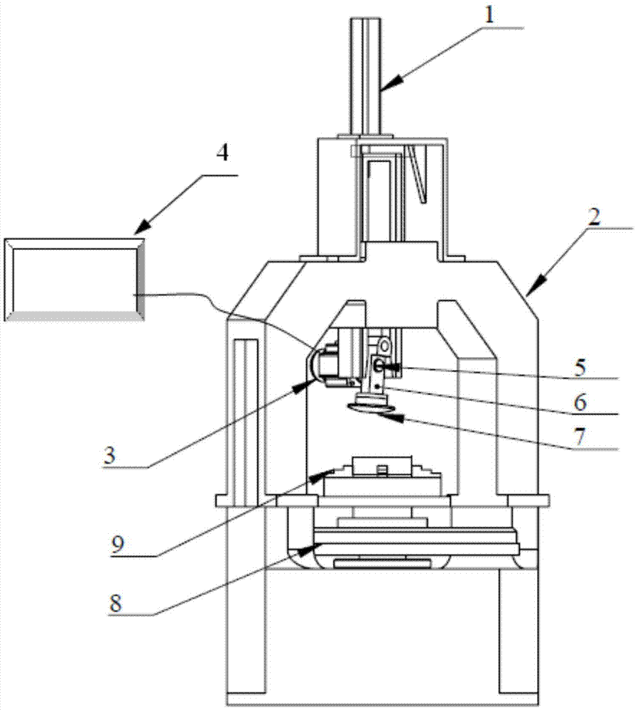
[0024] Example 1: Combining figure 1 The high-frequency vibration conformal polishing device illustrates this embodiment. This embodiment includes a precision cylinder 1, a gantry 2, a high-speed motor 3, a precision frequency converter 4, a cam 5, a swing arm 6, a grinding head 7, a rotary table 8 and the Workpiece 9. Precision cylinder 1, high-speed motor 3, cam 5, swing arm 6 and grinding head 7 are fixed on the gantry 2; gantry 2 is fixed directly above the rotary table 8; grinding head 7 is fixed directly below the swing arm; swing arm 6 is fixed On the cam 5; the high-speed motor 3 is connected to the cam 5, and the high-speed motor 3 drives the cam 5 to rotate; the rotation of the cam 5 drives the swing arm 6 to swing, so that the grinding head 7 fixed under the swing arm swings at a certain swing; the precision cylinder 1 Control the up and down movement of the cam 5, the swing arm 6 and the grinding head 7, so that the grinding head 7 fits the surface of the workpiec...

Embodiment 2

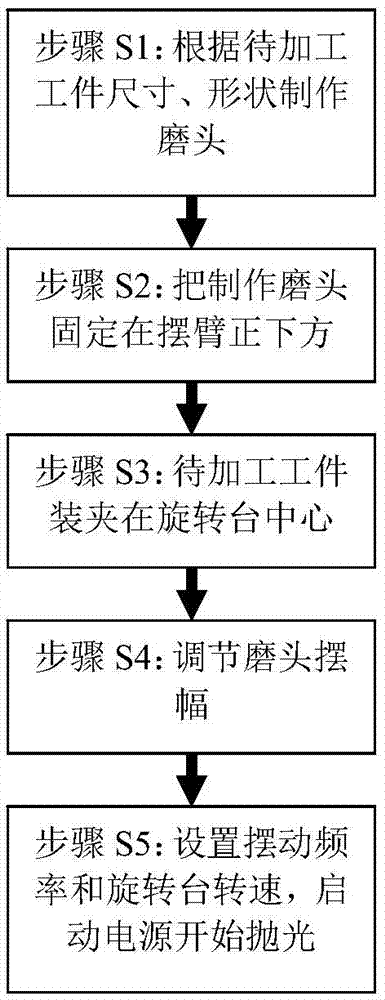
[0025] Embodiment two: combine figure 1 Describe this embodiment, this embodiment is realized through the following steps:

[0026] Step S1: making a polishing grinding head according to the shape of the workpiece to be processed. On the one hand, the polishing grinding head has a multi-layer structure, including a base layer, a flexible layer and a polishing layer, and the shape of the prepared polishing grinding head is consistent with the shape of the workpiece to be processed; On the one hand, the height of the grinding head should ensure that the radius of the swing arc is consistent with the radius of the shape of the workpiece to be processed. After assembly, the polished grinding head should be fixed directly under the swing arm;

[0027] Step S2: Clamp the workpiece so that the workpiece to be processed is clamped on the rotary table, and the center of the workpiece to be processed is required to be consistent with the center of the rotary table, and the eccentric err...


PUM


Abstract

The invention relates to a surface high-frequency vibration conformal machining device and method for an optical element. The method is based on parts such as a precision air cylinder, a gantry, a high-speed motor, a precision frequency converter, a cam, a swinging arm, a grinding head and a rotary platform, a polishing grinding head provided with a base layer, a flexible layer and a polishing layer is tightly attached to the surface of a workpiece with a certain pressure to carry out high-frequency vibration polishining. The high-frequency vibration conformal polishing method adopts full-aperture conformal coverage type polishing, is not limited by the surface characteristics of the workpiece to be machined, can polish various special-shaped optical surfaces, and achieves removal of high-speed materials on the surface of the workpiece to be machined, and the polishing efficiency is improved by 10-50 times compared with a common method. Meanwhile, a smoothness function is achieved for high frequency errors in the surface of the workpiece, and the surface high-frequency vibration conformal machining device and method for the optical element adapts to rapid polishing and medium and high frequency error suppression of small and large aperture planar, spherical and aspheric elements in the axial symmetry and special-shaped elements.

Description

technical field [0001] The invention relates to a high-frequency oscillation processing method and device for the surface of an optical element, belonging to the technical field of advanced optical manufacturing. Background technique [0002] Modern optical manufacturing engineering has significant extreme manufacturing characteristics, that is, the large scientific engineering of manufacturing extreme-scale or extremely high-function devices or functional systems under the background of extreme technical conditions. Our country is currently facing the completion of typical extreme optical development engineering tasks such as large-aperture telescope systems, nanoscale lithography systems, and high-power laser systems. The optical components of these systems require larger and larger apertures, higher and higher relative apertures, and greatly improved surface quality. Not only the improvement of PV and RMS in the traditional evaluation methods, but also many optical syste...

Claims


Application Information

Patent Timeline
IPC IPC(8): B24B1/04
CPCB24B1/04
Inventor 施春燕万勇建张亮徐清兰
Owner INST OF OPTICS & ELECTRONICS - CHINESE ACAD OF SCI
Why Eureka
Try Eureka