
Clamping and conveying device and method for wafer pin electroplating

A technology for conveying devices and wafers, which is applied in the direction of conveyor objects, transportation and packaging, etc. It can solve the problems of affecting product production efficiency, high product defective rate, low electroplating efficiency, etc., and achieves good clamping effect and high degree of intelligence , The effect of fast feeding speed

Inactive Publication Date: 2014-01-08
SICHUAN BLUE COLOR ELECTRONICS TECH
View PDF6 Cites 9 Cited by
  • Summary
  • Abstract
  • Description
  • Claims
  • Application Information

AI Technical Summary

Problems solved by technology

However, the current diode chip manufacturers completely complete the electroplating of the pins manually. The work is difficult, the work intensity is high, the product defective rate is high, and the electroplating efficiency is low, which directly affects the production efficiency of the product and cannot be applied to industrial assembly line production.

Method used


Image

  • Clamping and conveying device and method for wafer pin electroplating
  • Clamping and conveying device and method for wafer pin electroplating
  • Clamping and conveying device and method for wafer pin electroplating

Examples


Embodiment Construction

[0044] The technical solution of the present invention will be further described in detail below in conjunction with the accompanying drawings, but the protection scope of the present invention is not limited to the following description.

[0045] The clamping and conveying device for wafer pin electroplating includes a feeding device and a conveyor belt clamping device, and the feeding device includes a wafer disk pushing device and a wafer disk clamping and turning device.

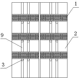
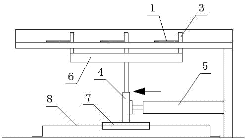
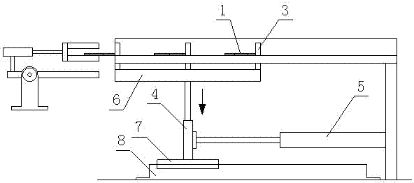
[0046] The wafer tray pushing device is used to push the wafer tray 1 to the wafer tray clamping and turning device, which includes a loading tray 2 and a wafer tray pushing mechanism. Such as figure 1 As shown, the loading tray 2 is provided with a push groove 9 matched with the movement direction of the column 3 . Such as figure 2As shown, the wafer disk pushing mechanism includes multiple rows of columns 3, jacking cylinders A4 and pushing cylinders 5, and the rows of columns 3 are fixedly installe...


PUM


Abstract

The invention discloses a clamping and conveying device and method for wafer pin electroplating. The clamping and conveying device comprises a feeding device, a conveying belt clamping device and a discharging device, wherein the feeding device comprises a wafer disc pushing device and a wafer disc clamping and turnover device, the wafer disc pushing device is used for pushing a wafer disc (1) to the wafer disc clamping and turnover device, the wafer disc clamping and turnover device is used for clamping and turning over the wafer disc (1) to the conveying belt clamping device to complete feeding, the conveying belt clamping device is used for clamping the wafer disc (1) to a conveying belt (17) to achieve wafer pin electroplating, and the discharging device is used for discharging the electroplated wafer disc (1) from the conveying belt (17). The clamping and conveying device is high in intelligent degree and improves production efficiency, when the wafer disc is fed in a clamped mode, the whole wafer disc clamping and turnover device moves in the conveying direction of the conveying belt at the speed matched with the conveying speed of the conveying belt, the effect that two clamping plates are static relative to the conveying belt can be ensured, friction is reduced, and abrasion on the wafer disc can be avoided.

Description

technical field [0001] The invention relates to a clamping and conveying device and method for wafer pin electroplating. Background technique [0002] Semiconductor diodes are often used in electronic circuits. It plays an important role in many circuits. It is one of the earliest semiconductor devices. Diodes are widely used and are usually used in rectification, isolation, voltage stabilization, polarity In circuits such as protection and coding control. The most important characteristic of a diode is unidirectional conductivity, that is, under the action of forward voltage, the on-resistance is very small; and under the action of reverse voltage, the on-resistance is extremely large or infinite. In the circuit, current can only flow in from the positive terminal of the diode and flow out from the negative terminal. [0003] Electroplating is the process of plating a thin layer of other metals or alloys on the metal surface by using the principle of electrolysis, which c...

Claims


Application Information

Patent Timeline
Patent Type & Authority Applications(China)
IPC IPC(8): B65G47/04B65G47/82B65G47/22B65G47/34
Inventor 黄职彬
Owner SICHUAN BLUE COLOR ELECTRONICS TECH
Learn More