Method for determining reaction potential of additive in lithium-ion cell electrolyte

A lithium-ion battery and electrolyte technology, applied in the direction of material electrochemical variables, AC/pulse peak measurement, etc., can solve the problem that the scan rate cannot correspond to the current, the data cannot play a correct guiding role, and the scan rate has a great influence, etc. Problems, to achieve significant production practice significance, enhance product use experience, and ensure the effect of work performance

Inactive Publication Date: 2014-01-08
TIANJIN LISHEN BATTERY
View PDF4 Cites 16 Cited by
  • Summary
  • Abstract
  • Description
  • Claims
  • Application Information

AI Technical Summary

Problems solved by technology

For this reason, it is necessary to detect the reaction potential of the additive in the electrolyte. At present, the method of cyclic voltammetry test is generally used. The potential value tested in this method is greatly affected by the scan

Method used


Image

  • Method for determining reaction potential of additive in lithium-ion cell electrolyte
  • Method for determining reaction potential of additive in lithium-ion cell electrolyte
  • Method for determining reaction potential of additive in lithium-ion cell electrolyte

Examples


Embodiment 1

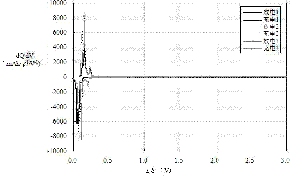
[0043] For the first battery system, in order to optimize the current and voltage process when the battery is formed for the first time, it is first necessary to investigate the film-forming reaction potential of the electrolyte additive on the negative electrode, so as to provide a reference for the charging cut-off voltage setting during the effective battery formation. First, the negative electrode active material of the first battery system is used to prepare the negative electrode sheet. The preparation process of the negative electrode sheet must be the same as that of the pole piece of the effective battery, or directly select the single-side coated part of the pole piece of the effective battery as the working electrode. In this example, a CR2430 button battery is used as the test unit of the first battery system. The single negative electrode of the first battery system is used as the working electrode, the lithium sheet is used as the counter electrode, and the button ...

Embodiment 2

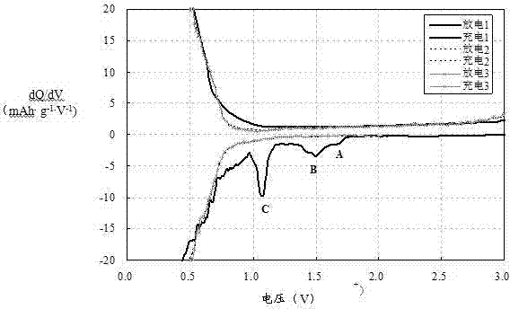
[0045] For the second battery system, in order to optimize the current and voltage process when the battery is formed for the first time, it is first necessary to investigate the film-forming reaction potential of the electrolyte additive on the negative electrode, so as to provide a reference for the charging cut-off voltage setting during the effective battery formation. The same method as in Example 1 was used to make a button battery as the test unit of the second battery system. According to the quality of the working electrode and the ratio of the slurry, the theoretical capacity was calculated to be 4.81 mAh, and it was charged and discharged with blue electric equipment. The current is set to 0.20 mA, that is, the current rate is 0.2 mA / 4.81 mAh = 0.04 C, the discharge cut-off voltage is set to 0.005 V, and the charge cut-off voltage is set to 3.0 V. The charge and discharge capacity and voltage data in the previous three cycle data are taken, Calculate the differentia...


PUM


Abstract

The invention discloses a method for determining a reaction potential of an additive in a lithium-ion cell electrolyte. The method comprises the steps of respectively taking a cathode half cell or an anode half cell as a test unit when the reaction potential of the additive in the lithium-ion cell electrolyte on a cathode or an anode of a lithium-ion cell needs to be measured; carrying out a charge-discharge test on the test unit and simultaneously detecting the cell capacity and the cell voltage of the test unit; carrying out differential treatment on the cell capacity Q and the cell voltage V, which are obtained through detection, of the test unit, calculating a differential value of the cell capacity Q on the cell voltage V, taking the differential value as a y coordinate, taking the cell voltage, which is obtained through detection, of the test unit as an x coordinate, and obtaining a test curve; obtaining a voltage value of each peak in the test curve according to the test curve. According to the method for determining the reaction potential of the additive in the lithium-ion cell electrolyte, disclosed by the invention, the reaction potential of the additive in a cell electrolyte can be accurately measured.

Description

technical field [0001] The invention relates to the technical field of battery detection, in particular to a method for measuring the reaction potential of additives in electrolyte solutions of lithium-ion batteries. Background technique [0002] At present, lithium-ion batteries have the incomparable advantages of other energy storage batteries, such as high energy density, light weight, and good safety performance. It is also widely used in bicycles and electric vehicles. [0003] Lithium-ion batteries have been widely used as a green energy source. With the different functional requirements in various application fields, the functional research on lithium-ion battery materials has gradually become the focus. For example, in low-temperature applications, materials and electrolytes are required to be uniform It can withstand the test of charge and discharge at low temperature, and suppress adverse side reactions to the greatest extent; in the field of high voltage applica...

Claims


Application Information

Patent Timeline
IPC IPC(8): G01R19/04G01N27/48
Inventor 李慧芳李飞高俊奎
Owner TIANJIN LISHEN BATTERY
Why Eureka
Try Eureka