In-line heat treatment device

A heat treatment device, series technology, applied in the direction of electrical components, semiconductor/solid-state device manufacturing, circuits, etc., can solve the problems of errors, reduce the productivity and reliability of the heat treatment process, and achieve the effect of improving productivity and reliability

Inactive Publication Date: 2014-01-08
TERASEMICON CO LTD
View PDF3 Cites 3 Cited by
  • Summary
  • Abstract
  • Description
  • Claims
  • Application Information

AI Technical Summary

Problems solved by technology

As a result, there is a disadvantage of lowering the productivity and reliabili

Method used


Image

  • In-line heat treatment device
  • In-line heat treatment device
  • In-line heat treatment device

Examples


Embodiment Construction

[0027] Hereinafter, the present invention will be described in detail with reference to the accompanying drawings and specific embodiments capable of implementing the present invention. These embodiments are described in detail so that those skilled in the art can fully practice. It should be understood that the various embodiments of the invention differ from each other, but are not mutually exclusive. For example, the specific shape, specific structure and characteristics of an embodiment described herein can also be implemented by other embodiments without departing from the spirit and scope of the present invention. In addition, it should be understood that the positions and arrangements of individual constituent elements in each disclosed embodiment may be changed without departing from the spirit and scope of the present invention. Therefore, the following detailed description is not intended to be limiting, and it is accurately stated that the protection scope of the p...


PUM


Abstract

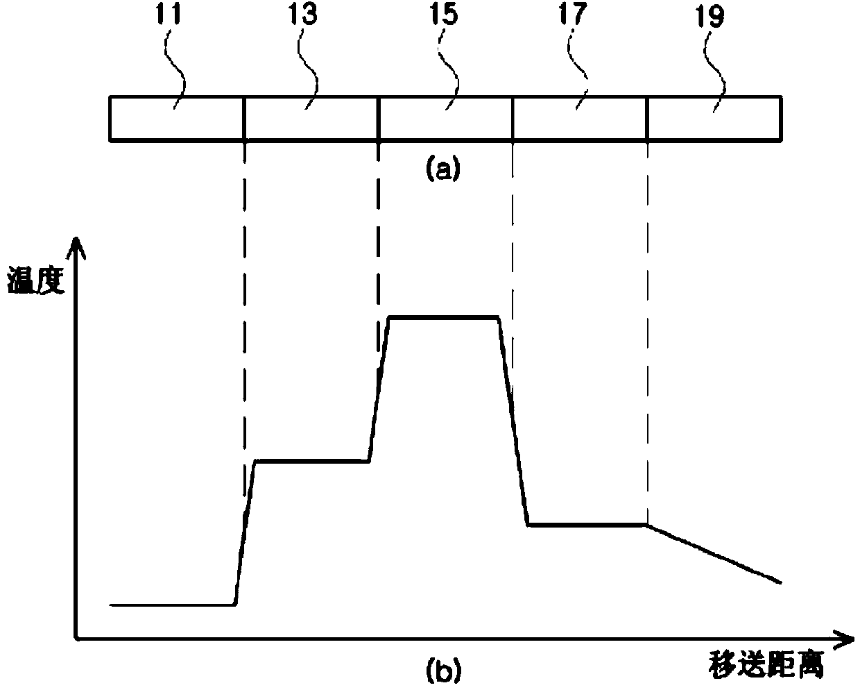
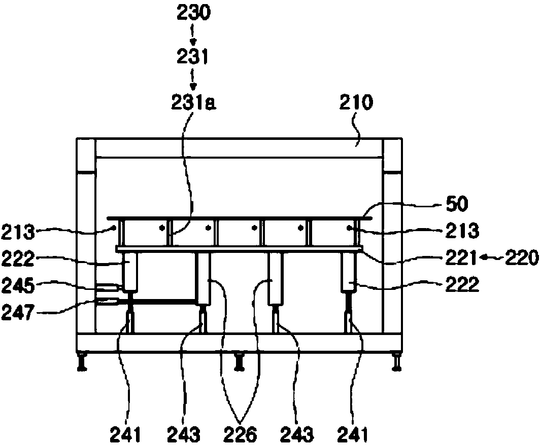
Disclosed is an in-line heat treatment device. The in-line heat treatment device according to the present invention has a plurality of heaters which are respectively installed in a plurality of furnaces, wherein each of the plurality of the heaters is controlled independently. Thus, since the temperature of each furnace and the temperature difference between mutually neighboring furnaces linearly change by forming a slow grade along the transferring direction of a substrate, there are no concerns regarding damage which may be caused by thermal shocks or thermal stress. Furthermore, the in-line heat treatment device according to the present invention enables the substrate to be lifted up when being transferred such that there is no friction between the substrate and components for transferring the substrate. Thus, since the generation of particles caused by the friction is prevented, there is no damage to the substrate due to the particles. In addition, the in-line treatment device according to the present invention prevents the components for transferring the substrate from being worn out by friction, thereby precisely transferring the substrate. Therefore, there are no errors during a heat treatment process for the substrate. Consequently, according to the present invention, productivity and reliability of the heat treatment process for the substrate are improved.

Description

technical field [0001] The invention relates to a tandem heat treatment device capable of improving the productivity and reliability of a heat treatment process. Background technique [0002] The annealing device used in the manufacture of flat panel display devices is a heat treatment device for crystallizing or changing the phase of a deposited film in order to improve the properties of the film deposited on the substrate. [0003] Thin-film transistors used as semiconductor layers in flat panel display devices, use deposition equipment to deposit amorphous (Amorphous) silicon on substrates such as glass or quartz, and dehydrogenate the amorphous silicon layer, and then inject it to form channels. Dopants such as Arsenic, Phosphorus or Boron. Then, a crystallization process is performed to crystallize the amorphous silicon layer having low electron mobility into a polysilicon layer having a crystal structure with high electron mobility. In order to crystallize the amorph...

Claims


Application Information

Patent Timeline
IPC IPC(8): H01L21/324H01L21/02
CPCH01L21/67173H01L21/67109H01L21/68742
Inventor 李炳一
Owner TERASEMICON CO LTD
Why Eureka
Try Eureka