Sand filter system
A technology of sand filter and sand filter tank, applied in the field of sand filter system, can solve the problems of short filtering time, unsatisfactory filtering effect, low utilization rate of filter layer, etc., and achieve good filtering effect.
- Summary
- Abstract
- Description
- Claims
- Application Information
AI Technical Summary
Problems solved by technology
Method used
Image
Examples
Embodiment 1
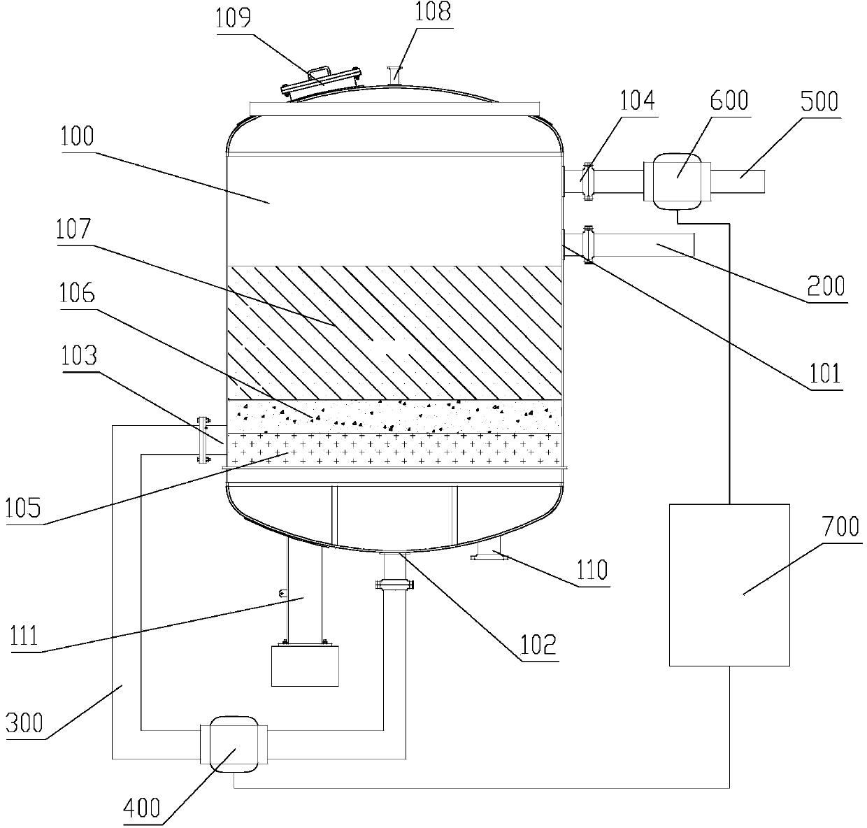
[0033] figure 1 It is a structural schematic diagram of the sand filtration system of this embodiment. As shown in the figure, the sand filter system includes a sand filter tank 100, the upper part of the sand filter tank 100 is provided with a positive washing inlet 101 and a backwash outlet 104, the lower part of the sand filter tank 100 is provided with a backwash inlet 103, and the bottom is opened There is a positive washing outlet 102 . The filter layers in the sand filter tank 100 are anthracite layer 107 , quartz sand layer 106 , and garnet layer 105 sequentially from top to bottom. The thickness of the garnet layer 105 is 25 cm, the thickness of the quartz sand layer 106 is 25 cm, and the thickness of the anthracite layer 107 is 100 cm.
[0034] The top of the sand filter tank 100 is provided with an exhaust port 108 and a viewing port 109 for manually observing the internal conditions of the sand filter tank 100 . A sewage outlet 110 for discharging sewage is open...
Embodiment 2
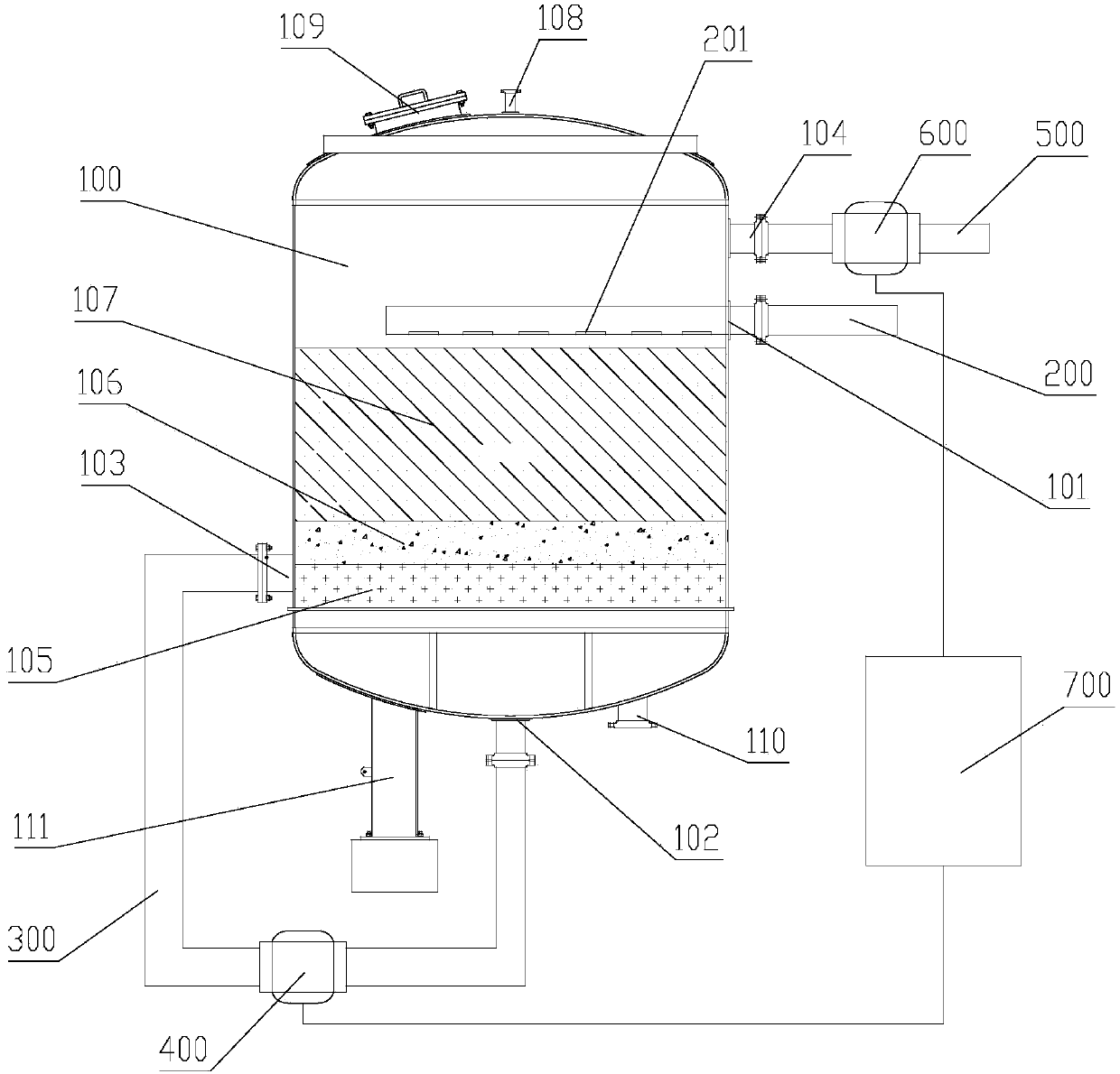
[0039] figure 2 It is a schematic diagram of the structure of the sand filter system of this embodiment. As shown in the figure, the basic structure of the sand filter system is the same as that of Embodiment 1, including a sand filter tank 100. The upper part of the sand filter tank 100 is provided with a positive washing inlet 101 and A backwash outlet 104, a backwash inlet 103 is opened at the bottom of the sand filter tank 100, and a positive wash outlet 102 is opened at the bottom. The positive washing inlet 101 is connected to the water inlet pipeline 200; the positive washing outlet 102 is connected to the backwashing inlet 103 through a transition pipeline 300, and the transition pipeline 300 is provided with a first valve 400; the backwash outlet 104 is connected to the water outlet pipeline 500, and the water outlet pipe A second valve 600 is provided on the road 500 .
[0040] The difference from Embodiment 1 is that the water inlet pipeline 200 of this embodiment...
Embodiment 3
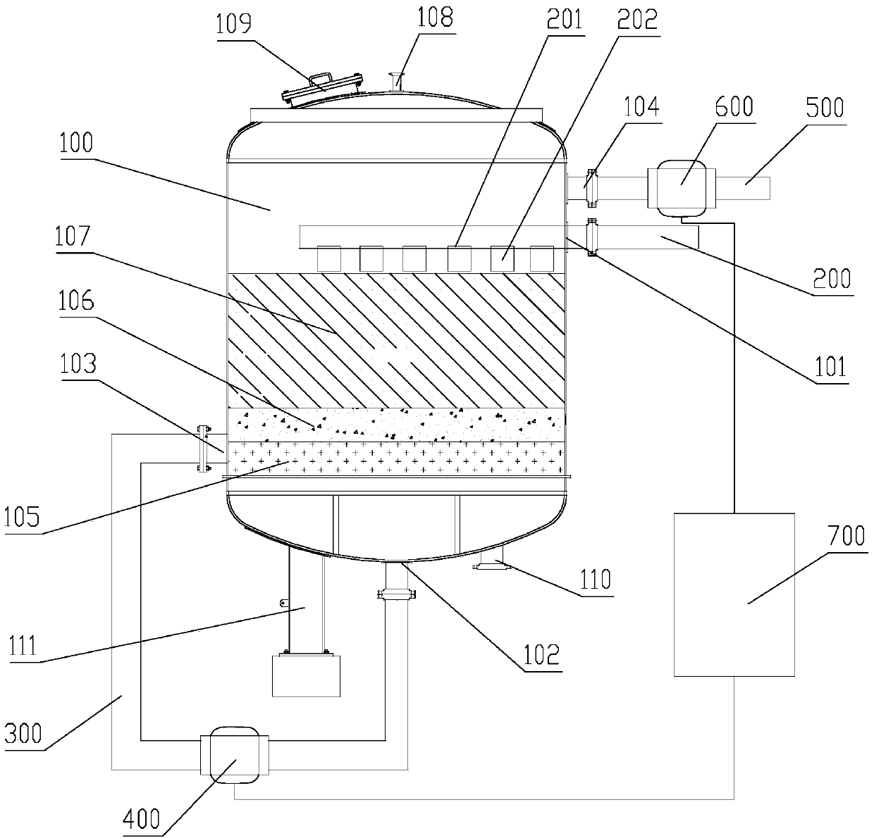
[0042] image 3 It is a structural schematic diagram of the sand filter system of this embodiment. As shown in the figure, the basic structure of the sand filter system is the same as that of Embodiment 2, including a sand filter tank 100. The upper part of the sand filter tank 100 is provided with a positive washing inlet 101 and A backwash outlet 104, a backwash inlet 103 is opened at the bottom of the sand filter tank 100, and a positive wash outlet 102 is opened at the bottom. The positive washing inlet 101 is connected to the water inlet pipeline 200; the positive washing outlet 102 is connected to the backwashing inlet 103 through a transition pipeline 300, and the transition pipeline 300 is provided with a first valve 400; the backwash outlet 104 is connected to the water outlet pipeline 500, and the water outlet pipe A second valve 600 is provided on the road 500 . The water inlet pipeline 200 extends into the sand filter tank 100 through the positive washing inlet 10...
PUM
| Property | Measurement | Unit |
|---|---|---|
| thickness | aaaaa | aaaaa |
| thickness | aaaaa | aaaaa |
| particle diameter | aaaaa | aaaaa |
Abstract
Description
Claims
Application Information
 - R&D
- Intellectual Property
- Life Sciences
- Materials
- Tech Scout
- Unparalleled Data Quality
- Higher Quality Content
- 60% Fewer Hallucinations
Browse by: Latest US Patents, China's latest patents, Technical Efficacy Thesaurus, Application Domain, Technology Topic, Popular Technical Reports.
© 2025 PatSnap. All rights reserved.Legal|Privacy policy|Modern Slavery Act Transparency Statement|Sitemap|About US| Contact US: help@patsnap.com


