Double-electric-arc spraying device

A spraying device and double-arc technology, which is applied in the field of double-arc spraying device, can solve problems such as insufficient deformation of molten particles, loss of cohesion between substrate and coating, insufficient temperature and kinetic energy, etc., and achieve energy utilization. High, conducive to workpiece forming, fast effect

Active Publication Date: 2014-01-15
无锡洲翔成套焊接设备有限公司 +1
View PDF4 Cites 0 Cited by
  • Summary
  • Abstract
  • Description
  • Claims
  • Application Information

AI Technical Summary

Problems solved by technology

However, in the traditional arc spraying, an arc is generated by two conductive nozzles, the local temperature will be relatively high, and the power and heat will be relatively large. When the spraying distance is too large, the temperature and kinetic energy of the molten particles hitting the surface of the substrate are not enough, and the molten particles cannot be generated. Sufficient deformation, the coating is loose and porous, the quality is poor, and the bonding strength is low; when the spraying distance is too small, the speed and temperature of the melting particles can be guaranteed to be high, but the substrate and coating are severely oxidized and the bonding strength is reduced. And as the degree of oxidation increases, it will even completely lose the adhesion between the substrate and the coating.

Method used


Image

  • Double-electric-arc spraying device
  • Double-electric-arc spraying device
  • Double-electric-arc spraying device

Examples


Embodiment approach 1

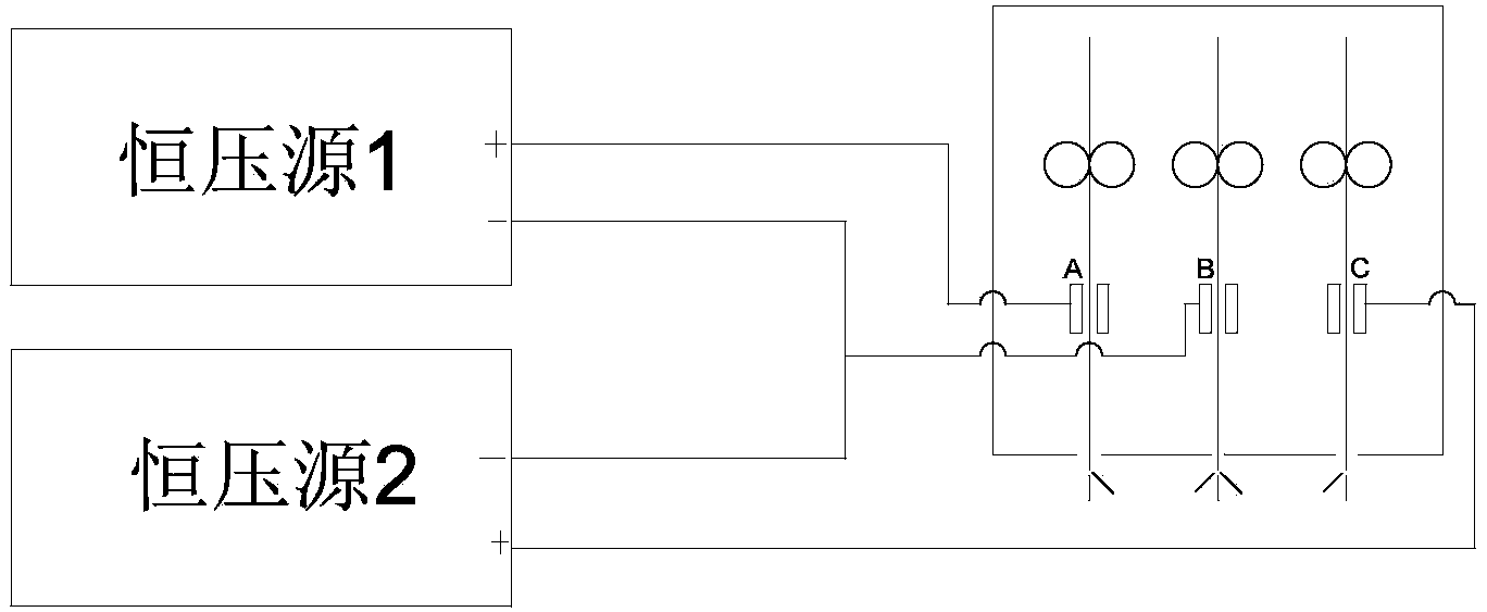
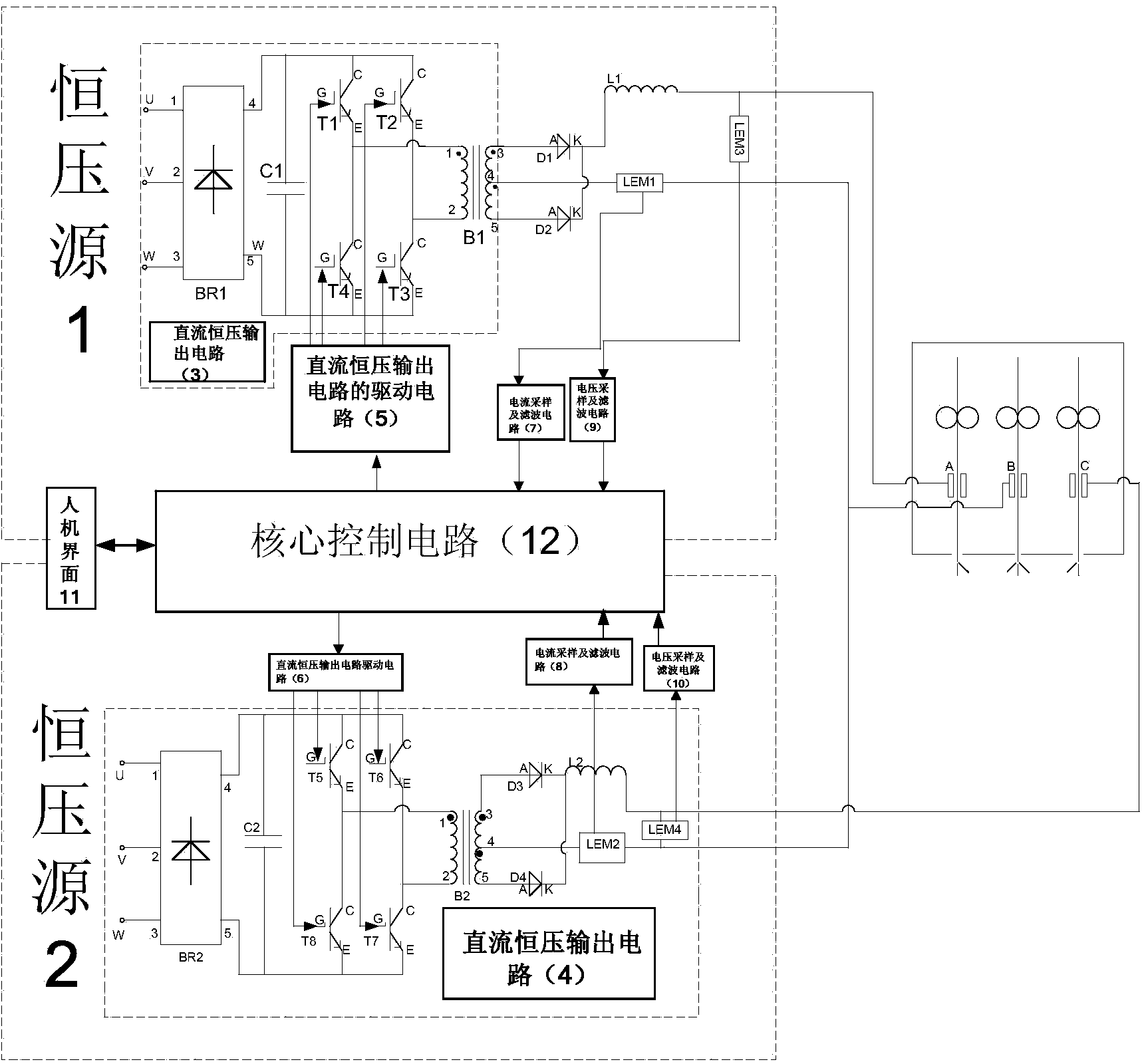
[0036] Such as image 3 As shown, the first constant voltage source circuit 1 in Embodiment 1 of the present invention includes: a DC constant voltage output circuit 3 , a drive circuit 5 for the DC constant voltage output circuit, a current sampling and filtering circuit 7 , and a voltage sampling and filtering circuit 9 . The second constant voltage source circuit 2 includes: a DC constant voltage output circuit 4 , a drive circuit 6 for the DC constant voltage output circuit, a current sampling and filtering circuit 8 , and a voltage sampling and filtering circuit 10 . The drive circuits 5 and 6 of the DC constant voltage output circuit are composed of IGBT dedicated drive chips M57962, the main control circuit 12 is composed of a single-chip microcomputer PIC30f2020, and the man-machine interface 11 is composed of conventional display circuits such as LED or LCD, and circuits such as keyboards and encoders.

[0037] Figure 5 It is the schematic diagram of the main circui...

Embodiment approach 2

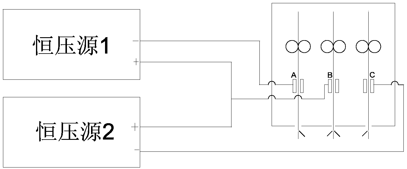
[0049] Such as Figure 4 As shown, in the second embodiment of the present invention, the circuit connected to the spraying gun has the same structure as that of the first embodiment, but the connection mode to the spraying gun is changed.

[0050] Image 6 It is the schematic diagram of the main circuit of the second embodiment. The negative output end of the DC constant voltage output circuit 3 is connected to the A connector of the three-wire spray gun, and the positive output end is connected to the B connector of the three-wire spray gun. The negative output end of the DC constant voltage output circuit 4 is connected to the C connector of the three-wire spray gun, and the positive output end is connected to the B connector of the three-wire spray gun.

[0051] Figure 9a When the power switch tubes T1 and T3 are turned on, the current flow of the primary and secondary sides of the transformer. The current flows out from the third end of the transformer B1, passes thr...


PUM


Abstract

The invention provides a double-electric-arc spraying device which comprises a first constant voltage source, a second constant voltage source and a three-wire spray gun structure. The two sets of the constant voltage sources are connected in parallel. When the positive output end of the first constant voltage source is connected with the A joint of the three-wire spray gun, the positive output end of the second constant voltage source is connected with the C joint of the three-wire spray gun and the negative output ends of the constant voltage sources are both connected with the B joint of the three-wire spray gun, electric arcs can continuously burns between the A joint and the B joint of the three-wire spray gun and between the B joint and the C joint of the three-wire spray gun; when the negative output end of the first constant voltage source is connected with the A joint, the negative output end of the second constant voltage source is connected with the C joint and the positive output ends of the constant voltage sources are both connected with the B joint, the electric arcs can continuously burns between the A joint and the B joint of the three-wire spray gun and between the B joint and the C joint of the three-wire spray gun. According to the invention, two electric arcs are generated by three current contact nozzles, and equivalently, a single conventional electric arc is divided into two electric arcs, so that the temperature and the power of each electric arc are reduced, the heat input is reduced, oxidation and corrosion can be reduced and high production efficiency is achieved.

Description

technical field [0001] The invention belongs to the technical field of thermal processing, in particular to a double-arc arc spraying device. Background technique [0002] Arc spraying is to use two sprayed metal wires as consumable electrodes, use the arc generated by the short circuit of the ends of the two metal wires to melt the wire, and use compressed gas to atomize the molten metal into micro-droplets, and make it Acceleration, a process of depositing a coating on the surface of a substrate at a very high speed. Arc spraying consists of four processes: the heat of the arc zone melts the end of the wire, the molten droplets fly in the arc zone, the metal droplets fly in the air, and the molten droplets deposit on the surface of the substrate. [0003] The application of arc spraying technology has achieved remarkable results in all walks of life. It is mainly used for the repair of major workpieces, wear-resistant and anti-corrosion, preparation of decorative coating...

Claims


Application Information

Patent Timeline
Patent Type & Authority Applications(China)
IPC IPC(8): C23C4/12C23C4/131
Inventor 黄鹏飞卢振洋徐旦徐惠忠李永格
Owner 无锡洲翔成套焊接设备有限公司
Why Eureka
Try Eureka