Creep test loading device for non-metal anti-floating anchor

An anti-floating bolt and creep test technology, applied in the test of foundation structure, construction, foundation structure engineering, etc., can solve the problems of time effect behavior of bolts, loss of anchoring force, etc. The effect of good performance and high test accuracy

Inactive Publication Date: 2014-01-15
QINGDAO TECHNOLOGICAL UNIVERSITY
View PDF5 Cites 17 Cited by
  • Summary
  • Abstract
  • Description
  • Claims
  • Application Information

AI Technical Summary

Problems solved by technology

In the prior art, the design of anchors is more concerned with the pull-out force of the anchor, that is, the displacement behavior of the anchor, and seldom cares about the time-effect behavior of the anchor. The design of permanent anchors is often carried out by increasing the safety factor, which brings There is a lot of blindness; under the long-term tension of the anchor, the loss of anchoring force is caused by creep deformation, and the relationship between its deformation and time is called the creep of the anchor, and the creep of the anchor is reflected by the creep coefficient At present, in engineering, more basic tests on anchors have been done, and less creep tests have been done. However, the long-term pull-out resistance of anchors is of great concern to engineers and technicians, especially in the design of permanent anchors. , the field anchor creep test is very important to study the time effect characteristics of anchor pullout, long-term pullout resistance is an essential parameter of permanent anchor, therefore, seek to design a non-metallic anti-floating anchor creep test The loading device has very important social and economic significance for determining the long-term pull-out capacity of the anchor and studying the time-effect characteristics of the pull-out of the anchor

Method used


Image

  • Creep test loading device for non-metal anti-floating anchor
  • Creep test loading device for non-metal anti-floating anchor
  • Creep test loading device for non-metal anti-floating anchor

Examples


Embodiment

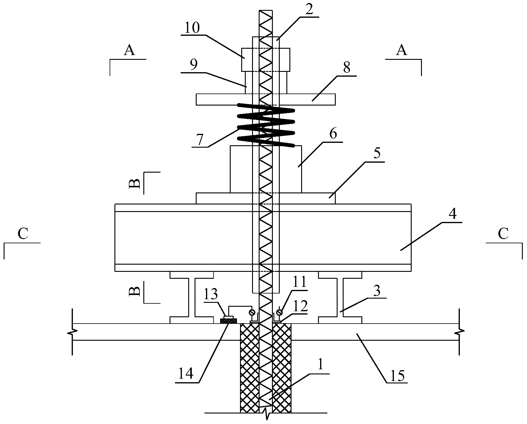
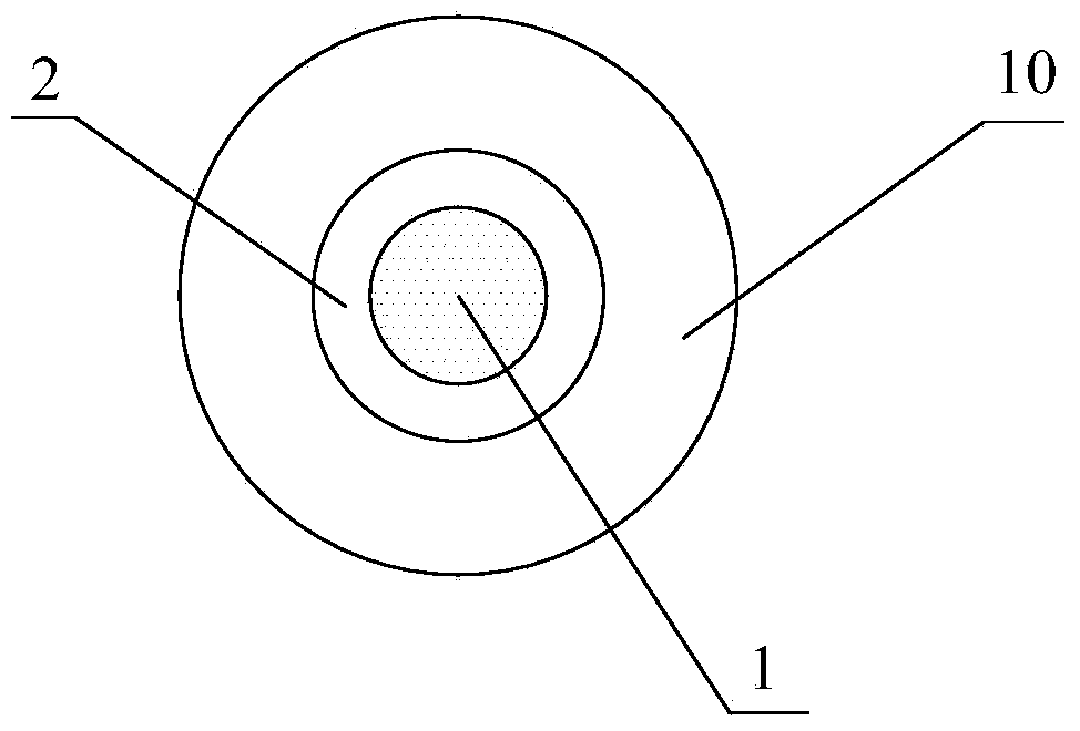
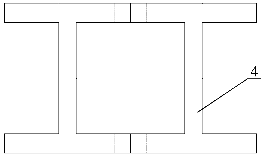
[0015] The main structure of this embodiment includes an anchor rod body 1, a steel sleeve 2, an I-beam 3, a reaction beam 4, a steel backing plate 5, a through-core jack 6, a spring 7, a steel plate 8, an anchor cable axial force gauge 9, Anchorage 10, dial indicator 11, L-shaped plexiglass 12, reference beam 13, concrete buttress 14 and concrete cushion 15; bolt body 1 is a glass fiber reinforced polymer (GFRP) full-threaded solid rod structure, which can Enhance the gripping force between the bolt body and the anchor body to provide sufficient anchoring friction; the inner diameter of the steel casing 2 is larger than the diameter of the GFRP bolt body 1, and the bolt body 1 and the steel casing 2 are filled with structural adhesive. They are closely bonded together to provide sufficient bonding force to prevent the damage of the material of the bolt body during the loading process. The length of the steel sleeve 2 is controlled by the design anchoring force; the webs of the...


PUM


Abstract

The invention belongs to the technical field of in-situ test equipment and relates to a creep test loading device for a non-metal anti-floating anchor. An anchor body is of a solid rod-shaped structure and is bonded with a steel casing pipe. H-shaped steel is perpendicular to a concrete cushion layer and is symmetrically arranged on the two sides of the anchor body. A counterforce beam is a box-type section formed by welding two pieces of H-shaped steel. The counterforce beam is provided with a steel base plate. The steel base plate, a penetrating jack, a spring, a steel plate, an anchor cable axial force meter and an anchorage device are stacked on the counterforce beam and arranged outside the steel casing pipe in a sleeved mode. The anchorage device is welded to the outside of the steel casing pipe. A dial indicator is arranged on L-shaped organic glass in an erecting mode. The L-shaped organic glass is arranged on the interface of the concrete cushion layer and the anchor body. A magnetic indicator base of the dial indicator is arranged on a standard beam arranged on a concrete buttress. The concrete buttress is arranged on the concrete cushion layer. The creep test loading device is simple in overall structure, convenient to install, high in testing precision and high in operability.

Description

Technical field: [0001] The invention belongs to the technical field of in-situ test equipment, and relates to a non-metallic anti-floating anchor rod creep test loading device, which is used for measuring and analyzing the creep deformation of the non-metallic anti-floating anchor rod. Background technique: [0002] With the development and utilization of urban underground space, the foundation depth of buildings continues to increase, and the problem of anti-floating becomes more and more prominent. The bolt has the advantages of strong stratum adaptability, dispersing stress, easy construction, cost saving, and large bearing capacity in hard rock and soil layers. The appearance of glass fiber reinforced polymer (GFRP) bolts has added a new means for geotechnical anchoring, especially the excellent corrosion resistance and anti-electromagnetic interference characteristics of GFRP materials, which solves the problems that plagued the geotechnical anchoring industry. Accord...

Claims


Application Information

Patent Timeline
Patent Type & Authority Applications(China)
IPC IPC(8): E02D33/00
Inventor 白晓宇张明义张亚妹闫楠
Owner QINGDAO TECHNOLOGICAL UNIVERSITY
Why Eureka
Try Eureka