
Microseismic monitoring analog system

A simulation system and microseismic technology, which is applied in the seismology of well logging records, etc., can solve the problems of rupture of the measured object, inability to simulate three-dimensional microseismic, and inability to use multiple times, and achieve the effect of accurate acquisition.

Active Publication Date: 2014-01-15
CHINA PETROLEUM & CHEM CORP +1
View PDF6 Cites 14 Cited by
  • Summary
  • Abstract
  • Description
  • Claims
  • Application Information

AI Technical Summary

Problems solved by technology

[0007] At present, the existing microseismic simulation system for hydraulic fracturing simulation experiments has the problem of low simulation degree, which is manifested in the following points:
[0008] ①The simulation degree of the model itself is low
If the pressure is continued, the object under test will eventually rupture completely
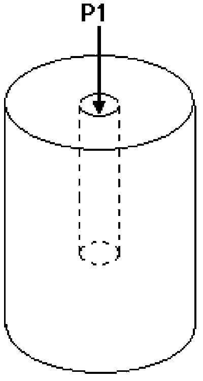
Therefore, the hole position of this model is relatively fixed, and it cannot be drilled multiple times. Generally, it cannot simulate the generation process of large cracks and cannot be used multiple times.
In addition, because the actual stratum in the field is often composed of multiple layers of rocks, this model cannot reflect the real stratum situation
[0014] ② Cannot simulate 3D microseismic
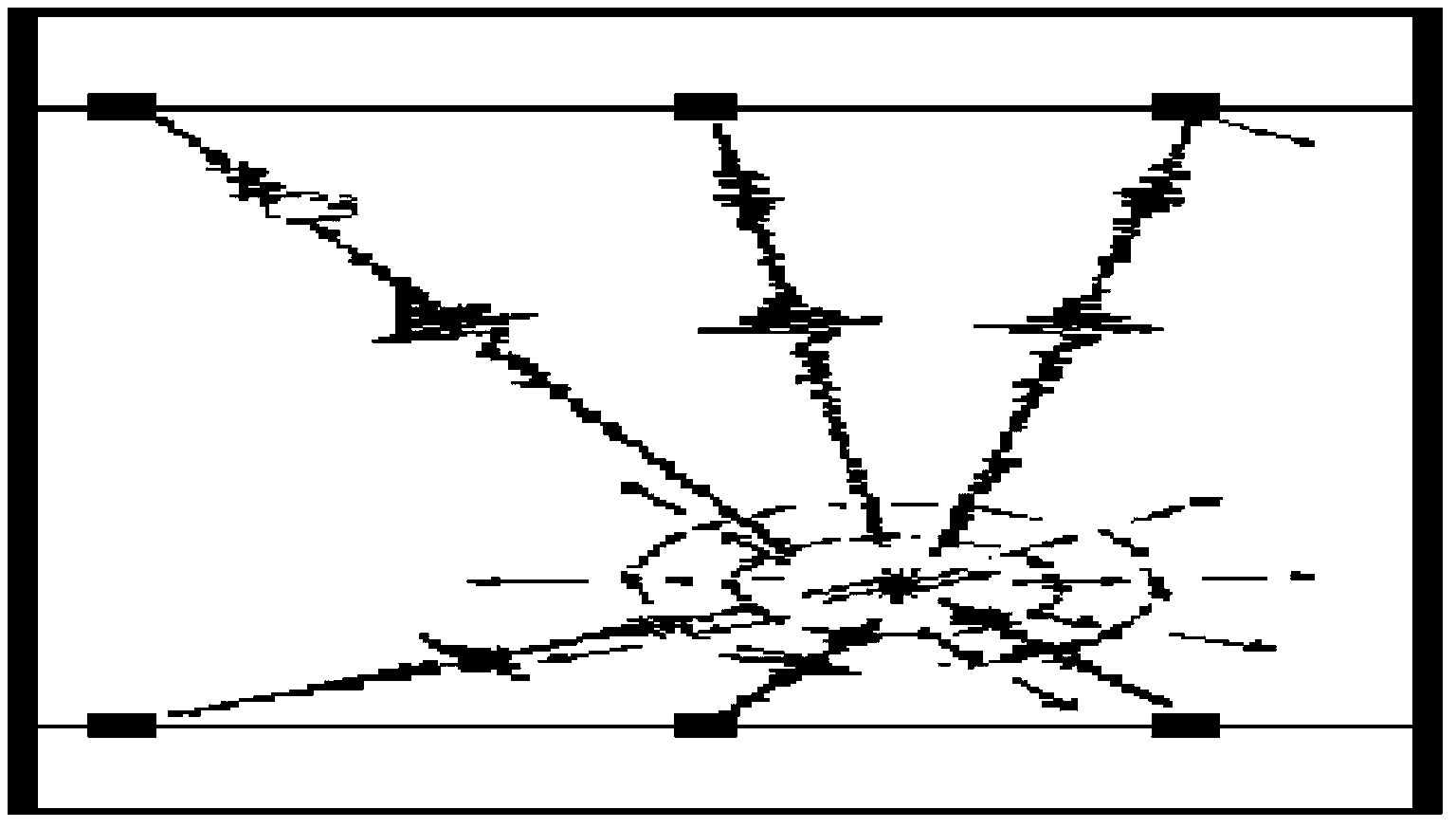
[0020] Because of this, when performing microseismic detection on the drilling site, it is generally necessary to lay more than dozens of vibration sensors on one surface for 3D detection. Therefore, placing fewer sensors means poor positioning accuracy and cannot truly simulate 3D microseismic in the field. exploration
[0021] ③Unable to perform broadband reception simulation
Its disadvantage is that on the one hand, the amplitude-frequency characteristics are not flat, and on the other hand, it cannot simulate the low-frequency signal response
[0023] ④Monitoring noise is high

Method used


Image

  • Microseismic monitoring analog system
  • Microseismic monitoring analog system
  • Microseismic monitoring analog system

Examples


Embodiment Construction

[0065] Below in conjunction with accompanying drawing, the present invention is described in further detail:

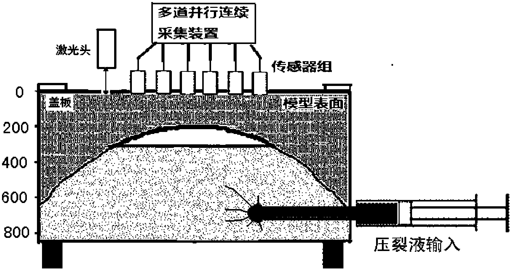
[0066] The principle diagram of the micro-seismic monitoring and simulation system of the present invention is as follows image 3 As shown, because the model is a cube or a cuboid with a square cross section, the sensors laid on the surface of the model should be laid on one surface, that is, there are multiple rows, but image 3 Only 6 sensors are given as an illustration, and various sensor arrangements such as 2x8 and 4x4 can be used for actual detection. The working process of the system is briefly described as follows: the fracturing fluid is pressurized and injected into the model under test, and the micro-seismic signal detection device is activated at the same time. When the pressure reaches the crack initiation pressure, a crack occurs. When a crack is generated, a micro-seismic sound wave signal is transmitted to the surroundings. The sensor group laid o...


PUM


Abstract

The invention provides a microseismic monitoring analog system which belongs to the field of micro-vibration generation and monitoring. The microseismic monitoring analog system comprises a simulation experiment fracturing device, a microseismic signal detection device and a microseismic simulation acquisition device. The simulation experiment fracturing device is used for generating fracturing fractures and sending out a microseismic signal. The microseismic signal detection device is used for detecting the microseismic signal and converting the microseismic signal to an analog electrical signal. The microseismic simulation acquisition device is sued for controlling the simulation experiment fracturing device and processing the analog electrical signal generated by the microseismic signal detection device. According to the invention, the problem that a general microseismic simulation monitoring system has poor simulation accuracy and poor precision is solved, the field well fracturing three-dimensional microseismic monitoring process can be simulated realistically, and the system has certain instructive effect on actual microseismic exploration.

Description

technical field [0001] The invention belongs to the field of micro-vibration generation and monitoring, and specifically relates to a micro-seismic monitoring simulation system, which can use micro-fracturing to generate and detect micro-seismic signals under indoor conditions, and is used to simulate micro-seismic signals generated by water fracturing in oil and gas wells And the detection process of microseismic signals. Background technique [0002] At present, most large oil and gas fields in my country have entered the late stage of exploitation, and the oil and gas resources in low permeability oil and gas fields are expected to become the driving force of future energy and economic development, and the oil and gas in these tight reservoirs need to be fracturing to achieve economical extraction. Fracturing is to use pressure to open one or several horizontal or vertical fractures in the formation, and use proppant to support the fractures, reduce the flow resistance of...

Claims


Application Information

Patent Timeline
Patent Type & Authority Applications(China)
IPC IPC(8): G01V1/40
Inventor 宗遐龄虞立王跃黄德娟王辉明
Owner CHINA PETROLEUM & CHEM CORP
Learn More