Modified electrical actuation of actuator for determining the time at which armature stops

An actuator and armature technology, applied in electrical control, engine control, electrical components, etc., can solve the problem of flat or too high offset curve, and achieve the effect of reducing tolerance

Active Publication Date: 2014-01-15
VTESCO TECH GMBH
View PDF11 Cites 12 Cited by
  • Summary
  • Abstract
  • Description
  • Claims
  • Application Information

AI Technical Summary

Problems solved by technology

Stroke tolerances lead to individual variations in the parabolic trajectory of the armatu...

Method used


Image

  • Modified electrical actuation of actuator for determining the time at which armature stops
  • Modified electrical actuation of actuator for determining the time at which armature stops
  • Modified electrical actuation of actuator for determining the time at which armature stops

Examples


Embodiment Construction

[0045] It should be pointed out that the embodiments described below are only a limited selection of possible implementation variants of the present invention.

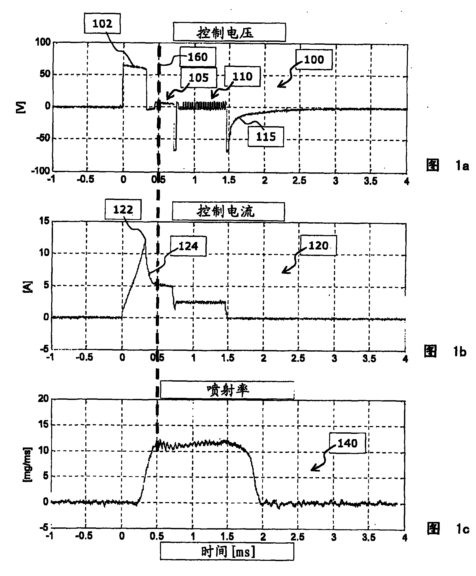
[0046] Figure 1a , 1b and 1c show (a) the control voltage 100 and the resulting control current 120 and (b) the resulting injection rate 140 over time for a serial control of a fuel injector with an amplification phase and a holding phase. It should be pointed out that, according to the exemplary embodiment shown here, the serial control corresponds to the known control of injectors with a boost phase. According to the embodiment shown here, this serial control is used as standard control, but it is replaced by a measurement control in the meantime, in order to be able to determine exactly the moment of armature stop after activation of the injector and to be able to The acquired information about the armature stop is used to optimize the subsequent serial control.

[0047] as from Figure 1a , 1b As can be seen i...


PUM


Abstract

The invention describes a method for operating an actuator having a coil and a displaceably mounted armature, which is driven by a magnetic field which is generated by the coil, in a measurement operating mode for ascertaining a time (260) at which the armature reaches its stop position after activation of the actuator. The method comprises (a) applying to the coil an actuation voltage signal (200) which is dimensioned in such a way that the expected time (260) at which the armature stops falls in a time window (206) in which a temporally constant voltage is applied to the coil, (b) detecting the time profile (220) of the intensity of the current which flows through the coil within the time window (206), and (c) determining the time (260) at which the armature reaches its stop position, based on an evaluation of the detected time profile (220) of the intensity of the current. The invention also describes a method for operating an actuator of this kind, wherein information about the stop time is obtained in a measurement operating mode and this information can be used in a series operating mode for the purpose of optimized actuation of the actuator. The invention also describes an apparatus and a computer program for ascertaining a time at which a displaceably mounted armature reaches a stop position after activation of an actuator.

Description

technical field [0001] The invention relates to the technical field of electromagnetically driven actuators having a coil to which a control signal can be applied and an armature mounted displaceably relative to the coil. The invention relates in particular to a method for operating an actuator in measuring mode of operation for the purpose of determining the moment at which an armature reaches its rest position after activation of the actuator, said actuator having (a) a coil and (b) a movable A ground-mounted armature driven by a magnetic field generated by a coil. Furthermore, the invention relates to a method for operating an actuator of this type, in which information about the moment of detent is acquired in the measurement mode and used in the serial mode for optimal control of the actuator. Furthermore, the invention relates to a device and a computer program for determining the moment at which a movably mounted armature of an actuator with a coil reaches a stop posit...

Claims


Application Information

Patent Timeline
IPC IPC(8): H01F7/18F02D41/20
CPCF02D41/20F02D2041/2055F02D2041/2058H01F7/1844H01F2007/185H01F7/18
Inventor M·科赫G·勒泽尔
Owner VTESCO TECH GMBH
Why Eureka
Try Eureka