Eureka AIR delivers breakthrough ideas for toughest innovation challenges, trusted by R&D personnel around the world.

Automatic dust removing device for cooler for forced oil circulation power transformer and dust removing method thereof

A technology for power transformers and strong oil circulation, which is applied in the direction of transformer/inductor cooling, chemical instruments and methods, cleaning methods and appliances, etc., and can solve the problem of temperature rise of power transformers with strong oil circulation, affecting heat dissipation efficiency, and reducing heat dissipation efficiency, etc. problem, to achieve the effect of cooling and heat dissipation, and to ensure the effect of heat dissipation efficiency

Active Publication Date: 2014-01-22
STATE GRID CORP OF CHINA +1
View PDF7 Cites 9 Cited by
  • Summary
  • Abstract
  • Description
  • Claims
  • Application Information

AI Technical Summary

Problems solved by technology

[0003] At present, the defects of this technology are as follows: First, large-scale power transformers and their coolers are mostly installed outdoors, and dust and sundries in the air are easily attached to the finned tubes, even large attachments, such as plastic films, newspaper sheets, etc. Foreign matter causes partial blockage, which seriously affects its heat dissipation efficiency, resulting in an abnormal rise in the temperature of the transformer body; second, with the increasing number of attachments, the heat dissipation efficiency of the cooler for strong oil circulation power transformers continues to decrease, and the temperature of strong oil circulation power transformers rises. High, affecting service life

Method used


Image

  • Automatic dust removing device for cooler for forced oil circulation power transformer and dust removing method thereof
  • Automatic dust removing device for cooler for forced oil circulation power transformer and dust removing method thereof

Examples


Embodiment 1

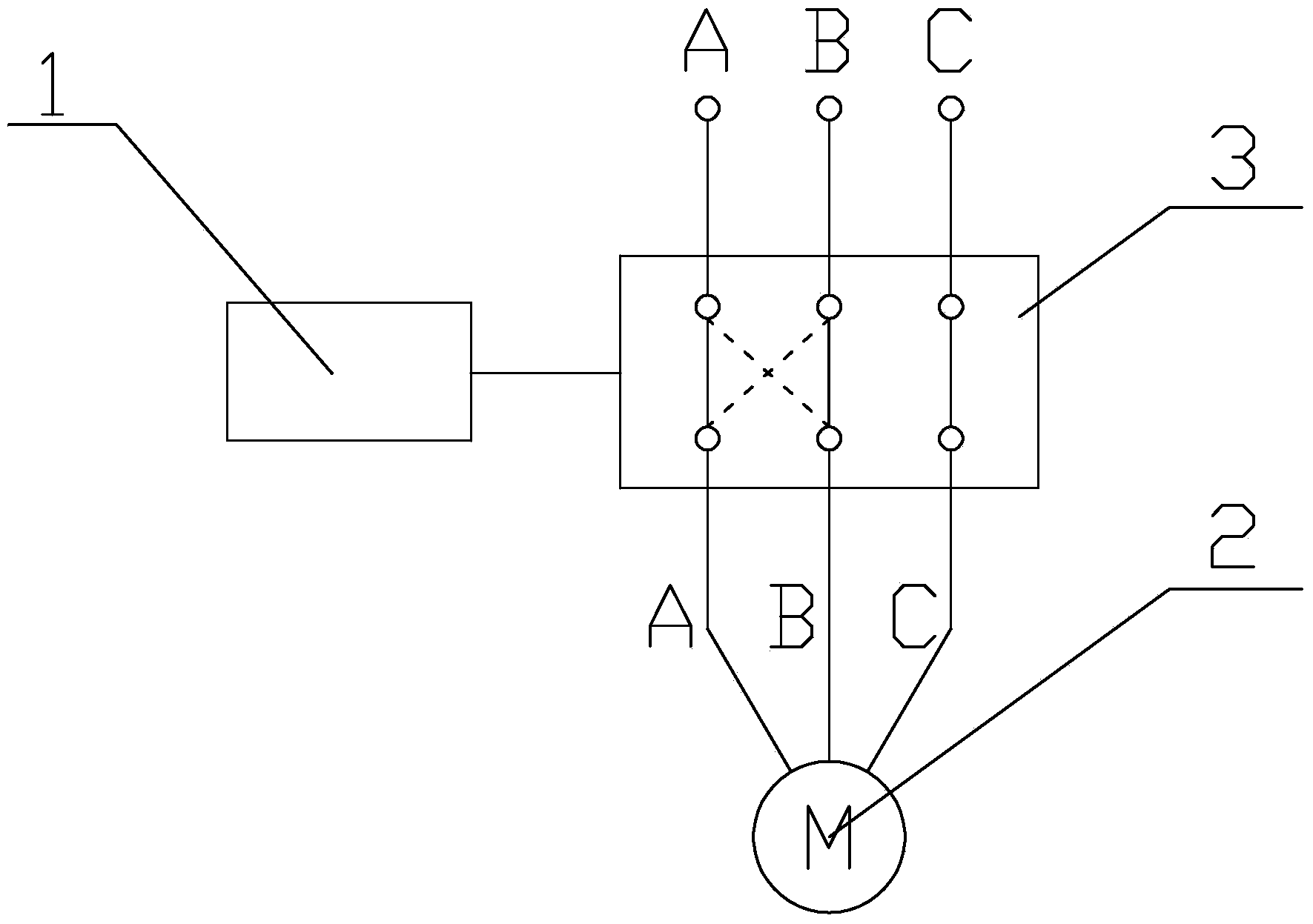
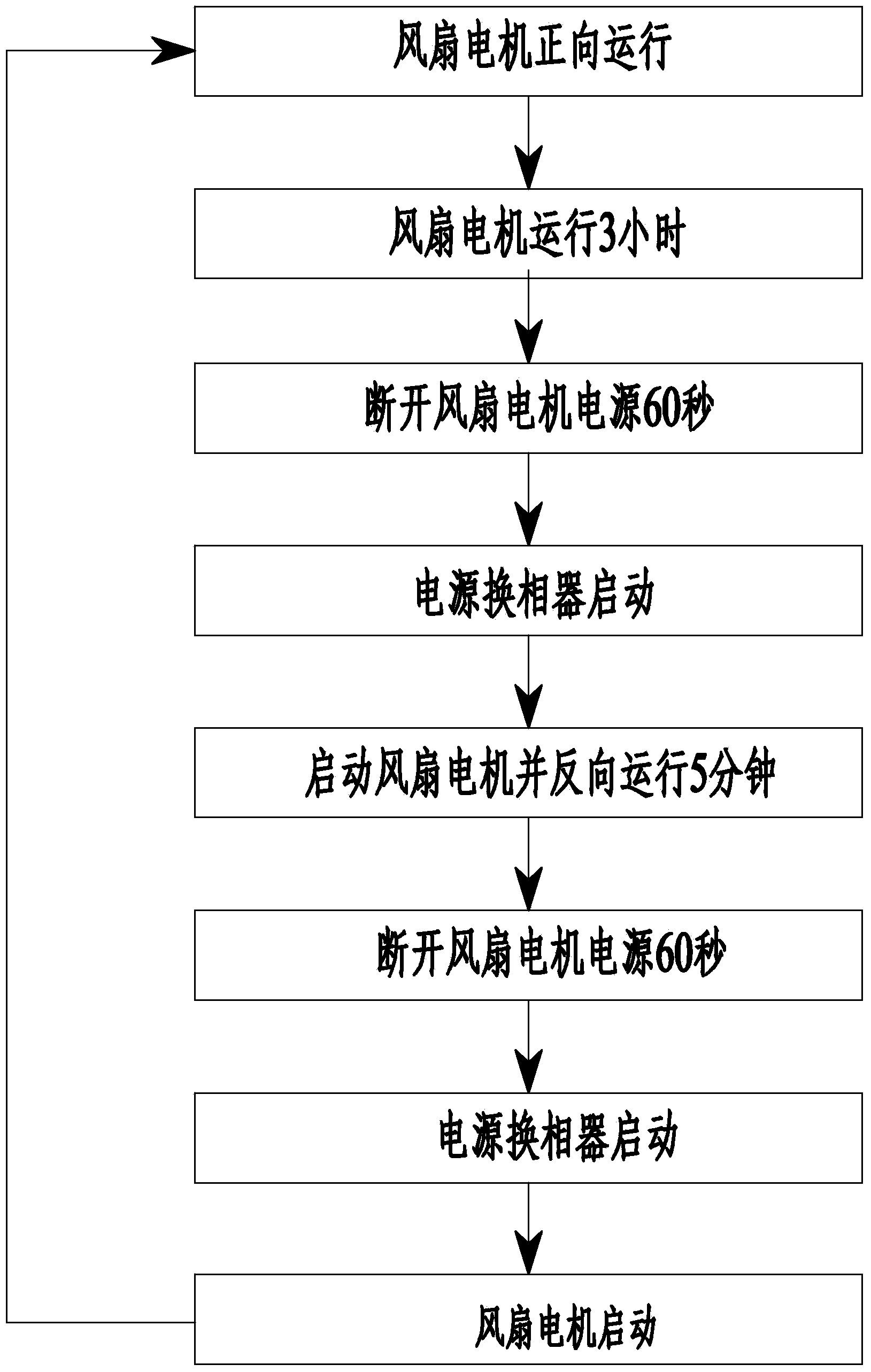
[0025] Embodiment 1: as figure 1 and figure 2As shown, the automatic dedusting device for the cooler of the strong oil circulation power transformer of the present invention comprises a strong oil circulation power transformer and a cooler for the strong oil circulation power transformer, and is provided with a controller 1, a commutation device, a voltage transformer, Current transformer, the signal output terminal of controller 1 is connected to the signal input terminal of the phase change device, and the three-phase input terminal of phase change device 3 is respectively connected to the low-voltage outlet terminal of the strong oil circulation power transformer through the voltage transformer and current transformer, and the strong oil circulation The cooler for the power transformer is provided with a fan driven by the motor 2 , and the three-phase output end of the commutation device 3 is connected to the power input end of the motor 2 . When the motor 2 driving the f...

Embodiment 2

[0026] Embodiment 2: On the basis of the structure described in Embodiment 1, the controller 1 is provided with a human-computer interaction panel, the human-computer interaction interface includes a display and a regulator, and the human-computer interaction interface is connected to the controller 1 through a communication line. According to the air pollution situation of the use site and the fan deceleration time of the cooler for the strong oil circulation power transformer, the forward rotation time, reverse time and deceleration time of the fan of the cooler for the strong oil circulation power transformer can be adjusted to improve the power of the strong oil circulation power transformer Heat dissipation efficiency of coolers for transformers.

Embodiment 3

[0027] Embodiment 3: On the basis of the structure described in Embodiment 2, a steel wire mesh cover is arranged outside the cooler for a power transformer with strong oil circulation. The large plastic paper can be blocked outside the steel wire mesh cover to prevent the plastic paper from contacting the finned tubes of the cooler for the strong oil circulation power transformer, because the temperature of the finned tubes of the cooler for the strong oil circulation power transformer is often high, which will make the The plastic sheet melted and stuck and couldn't be blown off.

[0028] Below in conjunction with the present invention, the embodiment of the automatic dedusting device for the cooler of the strong oil circulation power transformer is further described:

[0029] like figure 1 and figure 2 As shown, the automatic dedusting method for a cooler of a strong oil circulation power transformer according to the present invention, the method is as follows: the signa...


PUM


Abstract

The invention provides an automatic dust removing device for a cooler for a forced oil circulation power transformer and a dust removing method of the automatic dust removing device for the cooler for the forced oil circulation power transformer and belongs to the field of automatic dust removing equipment for coolers for forced oil circulation power transformers. The automatic dust removing device for the cooler for the forced oil circulation power transformer comprises the forced oil circulation power transformer and the cooler for the forced oil circulation power transformer and is provided with a controller, a phase changing device, a voltage transformer and a current transformer. The signal output end of the controller is connected to the signal input end of the phase changing device, the three-phase input end of the phase changing device is connected to the low-voltage wire outlet end of the forced oil circulation power transformer through the voltage transformer and the current transformer respectively, the cooler for the forced oil circulation power transformer is provided with a fan driven by a motor, and the three-phase output end of the phase changing device is connected to the power source input end of the motor. Dust and sundries on a fin tube of the cooler for the forced oil circulation power transformer can be effectively cleaned, the heat dissipation efficiency of the cooler for the forced oil circulation power transformer is improved, the maintenance workload is relieved, the operation temperature of the power transformer is reduced, and the expected service life of the power transformer is achieved.

Description

technical field [0001] The invention provides an automatic dedusting device for a cooler for a strong oil circulation power transformer and a dust removal method thereof, belonging to the field of automatic dedusting equipment for a cooler for a strong oil circulation power transformer. Background technique [0002] At present, in the substation of the power system, due to the current flow of each coil conductor and the existence of the electromagnetic field, the strong oil circulation power transformer in operation will generate power loss, mainly load loss, no-load loss and additional loss. Although the power transformer The operating efficiency is very high, but due to the large converted power, the loss is very objective. Large-scale power transformers can often reach tens to hundreds of kilowatts. These losses will be converted into powerful heat energy and spread outward. The forms of conduction, convection and radiation are transmitted in the iron core, coil, metal cl...

Claims


Application Information

Patent Timeline
IPC IPC(8): B08B9/023H01F27/08
CPCB08B9/023H01F27/08
Inventor 咸日常
Owner STATE GRID CORP OF CHINA
Why Eureka
Eureka Blog
Learn More