
Alloy melt hydrogen removal device and online hydrogen removal method thereof

A melt and alloy technology, applied in the field of metallurgy, can solve the problems of poor hydrogen removal effect and high cost of hydrogen removal, and achieve the effects of easy installation and replacement of equipment, low cost of hydrogen removal, and good application prospects

Active Publication Date: 2014-01-22
CHONGQING UNIV
View PDF4 Cites 3 Cited by
  • Summary
  • Abstract
  • Description
  • Claims
  • Application Information

AI Technical Summary

Problems solved by technology

[0008] In view of this, the object of the present invention is to provide a hydrogen removal device for alloy melt, which has a simple structure and good hydrogen removal effect, thereby solving the problems of poor hydrogen removal effect and high hydrogen removal cost in the prior art

Method used


Image

  • Alloy melt hydrogen removal device and online hydrogen removal method thereof
  • Alloy melt hydrogen removal device and online hydrogen removal method thereof
  • Alloy melt hydrogen removal device and online hydrogen removal method thereof

Examples


Embodiment 1

[0027] Embodiment 1 A kind of alloy melt dehydrogenation device

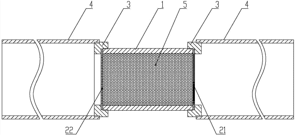
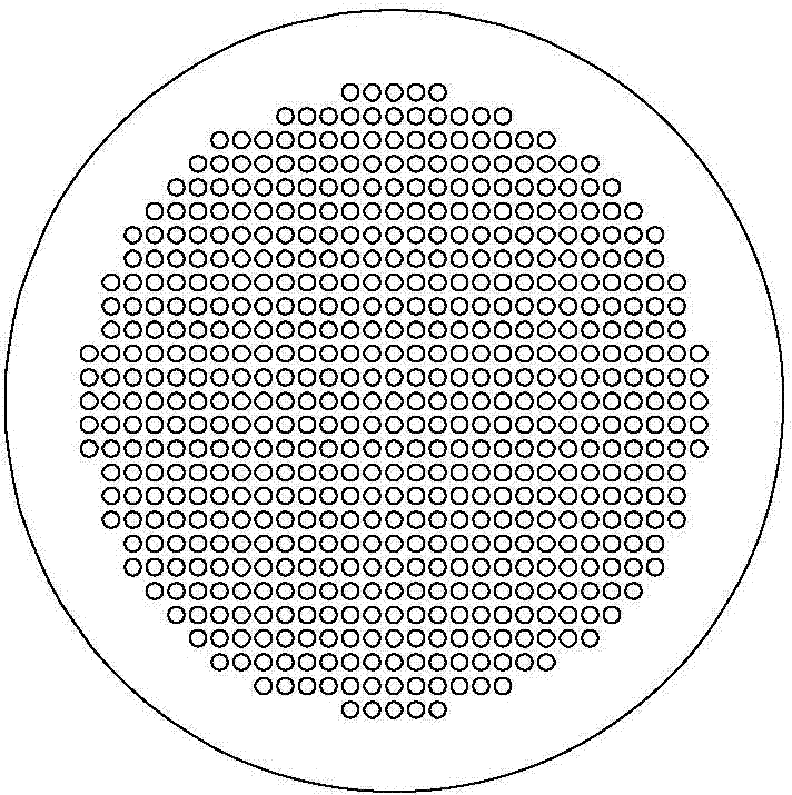
[0028] Such as Figures 1 to 2 As shown, the alloy melt hydrogen removal device of this embodiment includes a purification pipe 1, and the purification pipe 1 includes an alloy melt inflow end and an alloy melt outflow end, and the purification pipe 1 is uniformly filled with Mo content of 0.1 -2.0% Ti-Mo alloy particles 5, the outflow end of the alloy melt is provided with a first sealing plate 21 for filtering the Ti-Mo alloy particles 5, and the purification pipe 1 and the first sealing plate 21 are made of steel production. When in use, the alloy melt inflow end of the alloy melt dehydrogenation device can be vertically set upwards, and the alloy melt flows through the purification pipe 1 from top to bottom, and the Ti-Mo alloy particles 5 are carried out in the purification pipe 1. hydrogen absorption reaction. The alloy melt dehydrogenation device of the present invention has a simple structure, and com...

Embodiment 2

[0034] Embodiment 2 An online hydrogen removal method based on the alloy melt hydrogen removal device

[0035] An online hydrogen removal method based on the alloy melt hydrogen removal device in this embodiment includes the following steps: S1) passing one of the first sealing plate 21 and the second sealing plate 22 through the cylindrical connector 3 Connected to one end of the purification pipe 1; S2) Evenly filling the Ti-Mo alloy particles 5 into the purification pipe 1, the molybdenum element content in the Ti-Mo alloy particles 5 accounts for 0.1-2.0%, preferably 1.05%; S3 ) Connect the other one of the first sealing plate 21 and the second sealing plate 22 to the other end of the purification pipe 1 through the cylindrical connector 3; S4) Clean the installed first sealing plate 21 and the second sealing plate 22 The pipe 1 is screwed and fixedly connected to the melt flow pipe 3 through the cylindrical connector 3; S5) The alloy melt is passed into the melt flow pipe...


PUM


Abstract

The invention discloses an alloy melt hydrogen removal device and an online hydrogen removal method thereof. The device comprises a purifying tube which comprises an alloy melt inflow end and an alloy melt outflow end, Ti-Mo alloy particles are evenly placed into the purifying tube, and the alloy melt outflow end is provided with a first sealing plate used for filtering the Ti-Mo alloy particles. The alloy melt hydrogen removal device is simple in structure, convenient to install and replace, low in hydrogen removal cost, good in hydrogen removal effect and easy to apply to industrial production. Besides, the online hydrogen removal method based on the alloy melt hydrogen removal device is few in process procedure, equipment is convenient to install and replace, and the hydrogen removal effect is good. A magnesium alloy melt prepared by means of the device and the method can remarkably reduce the content of hydrogen in the melt, metallurgical quality of castings is improved, and the device and the method have good application prospect in industrial production.

Description

technical field [0001] The invention belongs to the field of metallurgy, in particular to an alloy melt hydrogen removal device and an online hydrogen removal method integrating physical and chemical reactions. Background technique [0002] The liquid quality of aluminum alloy or magnesium alloy (including the content of gas and inclusions, etc.) directly affects the quality of castings. During the smelting process of magnesium alloys, the dissolved gas is mainly hydrogen, and the presence of hydrogen tends to aggravate the formation of porosity. The hydrogen in the magnesium melt mainly comes from the moisture in the flux, the moisture adsorbed on the metal surface and the moisture brought in by metal corrosion. [0003] At present, the methods for removing hydrogen from magnesium alloy melts mainly fall into the following two categories: [0004] 1) The method of introducing gas mainly includes the method of introducing inert gas (such as argon or helium) and the method ...

Claims


Application Information

Patent Timeline
Patent Type & Authority Applications(China)
IPC IPC(8): C22C1/06
Inventor 蒋斌刘文君潘复生戴甲洪杨青山
Owner CHONGQING UNIV
Learn More