
Combined type refrigeration system and method based on coupling between direct cycle and reverse cycle

A refrigeration system and composite technology, applied in the direction of refrigerators, refrigeration and liquefaction, lighting and heating equipment, etc., can solve the problems of irreversible loss, large temperature difference of energy transmission, and can not be greatly improved, so as to reduce irreversible loss, Effects of COP improvement and thermal efficiency improvement

Active Publication Date: 2014-01-22
INST OF ENGINEERING THERMOPHYSICS - CHINESE ACAD OF SCI
View PDF5 Cites 13 Cited by
  • Summary
  • Abstract
  • Description
  • Claims
  • Application Information

AI Technical Summary

Problems solved by technology

[0003] The ammonia water absorption refrigeration cycle can use a lower temperature heat source, but when the heat source temperature is high, the COP of the absorption refrigeration cycle alone cannot be greatly improved. The main reason is that the temperature of the circulating working medium cannot increase with the temperature of the heat source. And rise, generally not more than 200 ℃
When the temperature of the heat source rises, there will be a large temperature difference in the energy transfer process, resulting in a large irreversible loss.

Method used


Image

  • Combined type refrigeration system and method based on coupling between direct cycle and reverse cycle
  • Combined type refrigeration system and method based on coupling between direct cycle and reverse cycle
  • Combined type refrigeration system and method based on coupling between direct cycle and reverse cycle

Examples


Embodiment Construction

[0035] In order to make the object, technical solution and advantages of the present invention clearer, the present invention will be described in further detail below in conjunction with specific embodiments and with reference to the accompanying drawings.

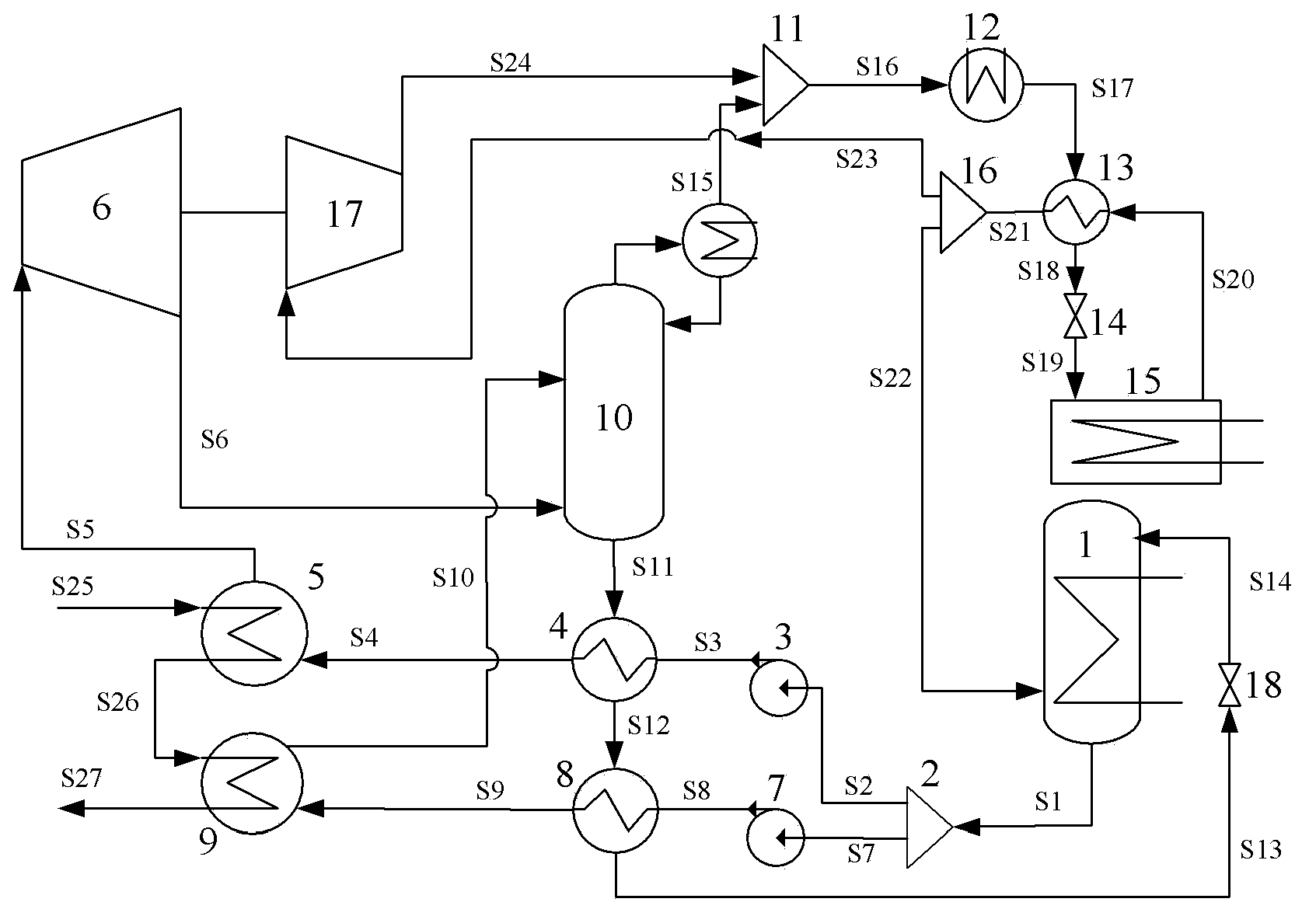
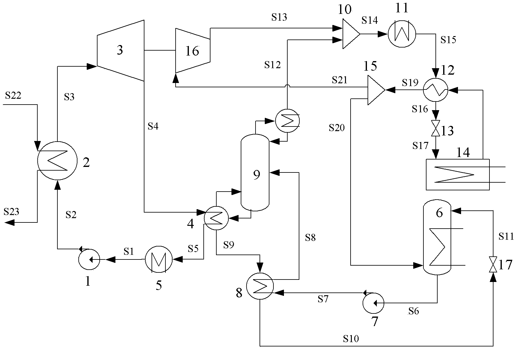
[0036]The invention provides a compound refrigeration system and method based on forward and reverse cycle coupling, using medium and low temperature waste heat or solar energy as a driving heat source. The system includes three sub-cycles, which are work sub-cycle, absorption refrigeration sub-cycle and compression refrigeration sub-cycle. The higher temperature part of the medium and low temperature heat source is used to drive the work sub-cycle to do work, and the lower temperature waste heat is used to drive the absorption refrigeration cycle. Refrigeration, while the heat exhausted by the work sub-cycle is also recycled by the absorption refrigeration sub-cycle, and the work done by the work sub-cycle drives the comp...


PUM


Abstract

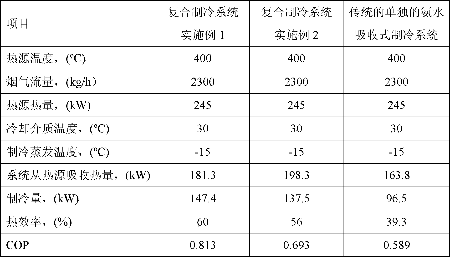
The invention discloses a combined type refrigeration system and method based on coupling between a direct cycle and a reverse cycle. According to the combined type refrigeration system and method based on coupling between the direct cycle and the reverse cycle, medium-and-low-temperature waste heat or solar energy or the like serves as a driving heat source. The combined type refrigeration system based on coupling between the direct cycle and the reverse cycle comprises three subcycles, wherein the subcycles comprise an acting subcycle, an absorption refrigeration subcycle and a compression refrigeration subcycle, the higher-temperature portion of the medium-and-low-temperature heat source is used for driving the acting subcycle to do work, the lower-temperature waste heat of the medium-and-low-temperature heat source is used for driving the absorption refrigeration subcycle to carry out refrigeration, meanwhile, discharged heat of the acting subcycle is recycled by the absorption refrigeration subcycle, and the work done by the acting subcycle drives the compression refrigeration subcycle to enable the work to be converted into cold energy to be output. Energy input of the whole system comprises the medium-and-low-temperature heat source, and product output of the whole system comprises the cold energy. Compared with an independent absorption refrigeration system, heat efficiency and COP of the combined type refrigeration system based on coupling between the direct cycle and the reverse cycle are greatly improved.

Description

technical field [0001] The invention relates to the technical field of medium and low temperature heat source refrigeration, in particular to an absorption-compression composite refrigeration system and method based on forward and reverse cycle coupling. Background technique [0002] Ammonia water absorption refrigeration technology is a refrigeration technology that can be driven by low-temperature waste heat resources or low-temperature renewable energy such as solar energy and geothermal energy. in other chemical processes. Low-temperature residual heat drives the generation process and rectification process to separate the concentrated solution into high-purity ammonia vapor and low-concentration dilute ammonia solution. The ammonia vapor is condensed into liquid ammonia in the condenser, and the liquid ammonia is subcooled, throttled and depressurized. It enters the evaporator for evaporation and refrigeration, and the evaporated ammonia vapor enters the absorber to be...

Claims


Application Information

Patent Timeline
IPC IPC(8): F25B25/02F25B27/00
Inventor 金红光韩巍孙流莉郑丹星林汝谋杨金福
Owner INST OF ENGINEERING THERMOPHYSICS - CHINESE ACAD OF SCI
Learn More