Integrated pulping system

An all-in-one, control system technology, applied in clay preparation devices, mixing operation control, mixing plants, etc., can solve the problems of unsuitable urban construction, poor work efficiency, time-consuming, etc., and save temporary construction work and transportation. cost, reduce labor intensity, and improve the effect of intelligent work

Active Publication Date: 2014-01-29
SINOHYDRO FOUND ENG
View PDF6 Cites 5 Cited by
  • Summary
  • Abstract
  • Description
  • Claims
  • Application Information

AI Technical Summary

Problems solved by technology

[0003] 1. The assembly and disassembly of the pulping station requires a lot of manpower and material resources, and the efficiency is low;
[0004] 2. The components in the whole pulping station need to be transported separately, and the transportation cost is high;
[0005] 3. After the assembly is completed, the volume is huge, the components in the pulping station are scattered, and it takes up a lot of space;
[0006] 4. During the transportation and storage of components, it is easy to cause damage and loss of components, which will affect the next use;
[0007] 5. The open pulping system seriously pollutes the construction site environment, especially not suitable for urban construction;
[0008] 6. The assembly of mutually independent components is troublesome and time-consuming, and debugging is required after each assembly, which seriously affects the construction period;
[0009] 7. The existing pulping system has a low degree of automation and poor work efficiency

Method used


Image

  • Integrated pulping system
  • Integrated pulping system
  • Integrated pulping system

Examples


Embodiment

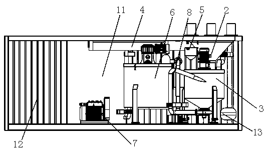
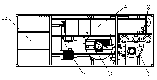
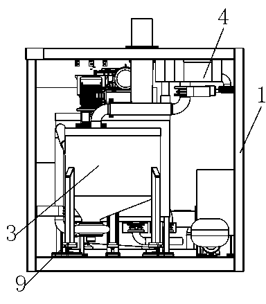
[0037] The existing pulping station has defects such as on-site assembly of various components at the construction site, which is not only troublesome, but also occupies a large area and has a low degree of automation in equipment operation. In order to overcome the defects of the prior art, this embodiment provides an integrated type pulping system, such as Figures 1 to 3 As shown, the working components included in the integrated pulping system are: pulping tank 3, pulp storage tank 6, pulp feeding device 7, water tank 4, centralized hopper 2, additive supply device 5, air compressor 13, etc. . On this basis, this embodiment also provides a container 1, in which all the above-mentioned components are installed, specifically, the container includes an integrated equipment installation room 11 and a control room 12, separated by a partition in the middle Concentrated into the hopper 2, slurry tank 3, water tank 4, admixture supply device 5, slurry storage tank 6 and slurry d...


PUM


Abstract

The invention discloses an integrated pulping system. The integrated pulping system mainly solves the problems of large floor area, waste of labor and time in disassembly and assembly, loss and damage of components in transportation, easiness in environmental pollution in work, low degree of automation and low effect in the conventional pulping station. The pulping system comprises an openable and closable container, a centralized feed hopper, a pulping tank, a water tank, an additive supply device, a pulp storage tank, a pulp delivery device, a power system and a control system, wherein the centralized feed hopper is arranged on the upper part in the container; the pulping tank is positioned below a discharge port of the centralized feed hopper; the water tank and the additive supply device are communicated with the upper part of the pulping tank through pipelines respectively; the pulp storage tank is communicated with the lower part of the pulping tank through a pipeline; the pulp delivery device is connected with the pulp storage tank; the power system is used for providing power for the operation of the integrated pulping system; the control system is used for controlling the operation of the integrated pulping system; the centralized feed hopper, the pulping tank, the water tank, the additive supply device, the pulp storage tank and the pulp delivery device are all arranged in the container. According to the integrated pulping system, the pulping system is highly integrated, the floor area of the pulping system is reduced, and the degree of automation of the equipment is improved.

Description

technical field [0001] The invention belongs to the technical field of foundation treatment engineering construction, and relates to pulping equipment, in particular to an integrated pulping system. Background technique [0002] The pulping system is composed of multiple components assembled. At present, the pulping system used in the construction of the foundation treatment project is an open system, and the equipment is independent of each other. Before the project starts, staff are required to temporarily build and assemble the pulping station. Work, it mainly has the following defects: [0003] 1. The assembly and disassembly of the pulping station requires a lot of manpower and material resources, and the efficiency is low; [0004] 2. The components in the whole pulping station need to be transported separately, and the transportation cost is high; [0005] 3. After the assembly is completed, the volume is huge, the components in the pulping station are scattered, an...

Claims


Application Information

Patent Timeline
Patent Type & Authority Applications(China)
IPC IPC(8): B28C9/02
CPCB28C9/02
Inventor 孙仲彬李文书杨振中杜晓麟侯国成朱勇
Owner SINOHYDRO FOUND ENG
Why Eureka
Try Eureka