Eureka AIR delivers breakthrough ideas for toughest innovation challenges, trusted by R&D personnel around the world.

led substrate and high voltage led lamps

A technology for LED substrates and LED lamps, which is applied to lighting devices, light sources, and components of lighting devices, etc., can solve problems such as increased resistance, circuit imbalance, and short-circuit between positive and negative electrodes, so as to improve withstand voltage requirements and reduce insulation. The effect of requiring and avoiding production costs

Active Publication Date: 2016-03-09
SICHUAN JIUZHOU OPTOELECTRONIC TECH CO LTD
View PDF5 Cites 0 Cited by
  • Summary
  • Abstract
  • Description
  • Claims
  • Application Information

AI Technical Summary

Problems solved by technology

If the heat conduction circuit board of the LED is broken down, it is considered that the LED lamp does not meet the requirements and cannot pass the safety high voltage test
[0004] In order to meet the safety test requirements, the existing methods such as a method for an LED lamp to pass the safety high-voltage test disclosed in Chinese patent CN103162259A and a high-voltage LED lamp, which adopt heat conduction between the output end of the driving power supply and the LED lamp The circuit between the metal base layers of the circuit board is connected with a bleeder resistor to improve the high-voltage resistance of the lamp. However, this method has the following problems: First: If the positive pole / negative pole is connected to the aluminum substrate, the aluminum substrate has Connected to the metal case, the metal case is connected to the earth, causing the positive / negative connection of all lamps to be short circuited, causing the circuit to be unbalanced
Second: If the positive pole and / or negative pole are connected to a resistor at the same time, the resistor becomes a load, resulting in a decrease in system efficiency
Third: Increasing the resistance will increase the material cost and processing cost. The more components, the higher the risk of failure

Method used


Image

  • led substrate and high voltage led lamps
  • led substrate and high voltage led lamps
  • led substrate and high voltage led lamps

Examples


Embodiment Construction

[0020] The technical solutions in the embodiments of the present invention will be clearly and completely described below in conjunction with the drawings in the embodiments of the present invention, and similar component numbers in the drawings represent similar components. Apparently, the embodiments described below are only a part of the embodiments of the present invention, rather than all the embodiments. Based on the embodiments of the present invention, all other embodiments obtained by persons of ordinary skill in the art without creative efforts fall within the protection scope of the present invention.

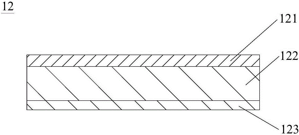
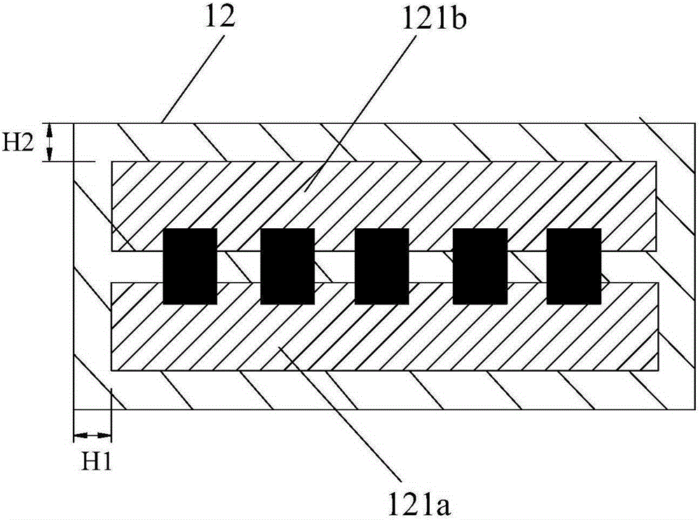
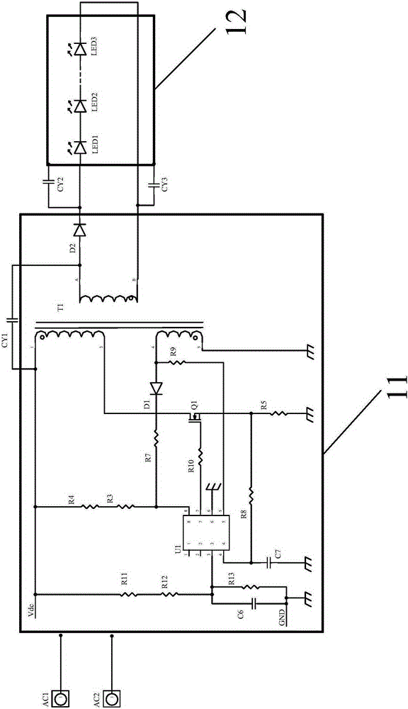
[0021] refer to Figure 1 to Figure 3 , the high voltage LED lamp of this embodiment includes a driving power supply 11 , an LED substrate 12 and a heat dissipation housing (not shown in the figure), wherein the output end of the driving power supply 11 is connected to several LEDs on the LED substrate 12 . The LED substrate 12 of this embodiment is an aluminum subs...


PUM


Abstract

The invention discloses a high voltage resistant LED lamp which comprises a driving power supply, a heat dissipation casing and an LED substrate. The LED substrate comprises a circuit layer, an insulating layer and a metal layer and is characterized in that the circuit layer comprises positive pole copper foil and negative pole copper foil which are separated from each other, the total area of the copper foil meets the equation that S>=4piKd*CY1 / epsilon, wherein S is the sum of the area of the positive pole copper foil and the negative pole copper foil, K is a static parameter of the insulating layer, d is the thickness of the insulating layer, CY1 is capacitance of the driving power supply, and epsilon is a dielectric constant of the insulating layer. According to the high voltage resistant LED lamp, distributed capacitance of an aluminum substrate is increased by increasing the area of the positive pole copper foil and the negative pole copper foil, voltage applied to two ends of the aluminum substrate during in withstanding voltage tests is reduced, the lamp can meet the withstanding voltage test requirements on the conditions that components are not increased, the high voltage resistant LED lamp is safe and reliable, and the cost is reduced.

Description

technical field [0001] The invention relates to the technical field of LEDs, and more specifically relates to an LED substrate and a high-voltage-resistant LED lamp. Background technique [0002] LED is a semiconductor device that can directly convert electrical energy into light energy. It has changed the principle of tungsten filament luminescence of incandescent lamps and three-based toner luminescence of energy-saving lamps, and uses electric field luminescence. In modern society, because of the advantages of LEDs such as small size, long life, high luminous efficiency, no radiation and low power consumption, people are using LED lighting more and more widely. [0003] At present, the existing LED lamps generally include a metal lamp housing and a PC cover arranged on the metal lamp housing. The metal lamp housing is provided with an LED substrate (heat-conducting circuit board) and a driving power supply. The output end of the driving power supply is connected to the he...

Claims


Application Information

Patent Timeline
Patent Type & Authority Patents(China)
IPC IPC(8): F21V23/02F21Y115/10
Inventor 王兴华汪华
Owner SICHUAN JIUZHOU OPTOELECTRONIC TECH CO LTD
Why Eureka
Eureka Blog
Learn More