Implantable side-pumping coupling method

A side-pumped and implanted technology, which is applied to laser components, electrical components, lasers, etc., can solve the problems of difficult process, increased product volume, and large impact, so as to solve the problem of thinning optical fibers, improving coupling efficiency, The effect of solving fiber warpage

Active Publication Date: 2014-01-29
CHINA ELECTRONICS TECH GRP NO 46 RES INST
View PDF9 Cites 7 Cited by
  • Summary
  • Abstract
  • Description
  • Claims
  • Application Information

AI Technical Summary

Problems solved by technology

The end-pumping method has high coupling efficiency, but it has the following disadvantages: first, the fiber end face is easily burned when high-power pump light is injected, which limits the output power of the fiber laser; second, the double-clad active fiber has only two end faces for use as The pump coupling end face not only limits the number of pump sources that can be used, but also affects the freedom of the entire laser structure design
[0005] Analyzing the above-mentioned side pump coupling methods, there are obvious deficiencies: V-groove side pump coupling, embedded mirror pump coupling, and angle grinding and polishing side pump coupling have the disadvantages that the process is difficult and difficult to implement, and the pumping Coupling efficiency is unstable and greatly affected by the process
The disadvantage of the side-coupling method (US Patents US7660034, US7221822) in which the pump fiber and the active fiber are in contact with each other is that the pump coupling efficiency is low. If the length of the pump fiber and the double-clad active fiber is increased to improve the coupling efficiency, It will also reduce the nonlinear threshold of the double-clad active fiber, resulting in obvious nonlinear
The disadvantage of the light source side coupling method of the double-clad fiber whose outer cladding is the pump optical waveguide (Chinese patent CN1284013) is that a prism needs to be used to couple the pump light, so that full-fiber integration cannot be achieved, which not only increases the volume of the product but also Affect the stability of the optical path
The side coupling method of the pump light source (Chinese patent CN210590) is to wind the multimode fiber and the double-clad active fiber in the coupling area to keep the fiber in contact. The disadvantage of this method is that the multimode fiber is easy to warp and pull Taper treatment will cause the fiber to become thinner and increase the loss of signal light and pump light
The structure of the laterally pumped fiber and its manufacturing method (Chinese patent CN 201110250593) optimizes the coupling methods of US patents US7660034 and US7221822, but the refractive index distribution of the passive fiber and the double-clad active fiber required by the method is basically difficult. Realization, and there is also the problem of low coupling efficiency, the remaining pump light that is not coupled from the passive fiber is a great hidden danger to the stable operation of the fiber laser

Method used


Image

  • Implantable side-pumping coupling method
  • Implantable side-pumping coupling method
  • Implantable side-pumping coupling method

Examples


Embodiment Construction

[0028] Below in conjunction with accompanying drawing, specific embodiment of the present invention is described in further detail:

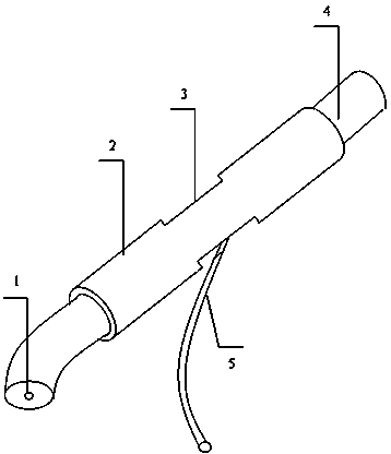
[0029] like figure 1 As shown, an implantable side pump coupling method includes a double-clad active fiber for generating laser light or amplifying laser light; and a multimode fiber 5 for connecting the pump source; the multimode fiber 5 The pump light is coupled into the double-clad active optical fiber by implanted side pumping method.

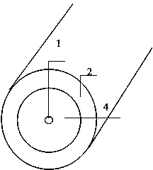
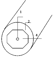
[0030] like figure 2 , image 3 , Figure 4 As shown, the double-clad active optical fiber includes a silica core 1 doped with rare earth ions, a pure silica inner cladding 4 and a low-refractive-index coating 2 . The refractive index of the coating of the double-clad active optical fiber is one of 1.31 and 1.37, and the curing method is ultraviolet curing or thermal curing.

[0031] The pure silica inner cladding shape of the double-clad active fiber is circular (such as figure 2 ), square (such as ...


PUM


Abstract

The invention discloses an implantable side-pumping coupling method. The implantable side-pumping coupling method is characterized by including a double-cladding active optical fiber and at least one multimode fiber, wherein the double-cladding active optical fiber is used for producing laser or amplifying the laser, and the multimode fiber is used for being connected with a pumping source. Pumping light is coupled into the double-cladding active optical fiber through the multimode fiber in the implantable side-pumping coupling method. The method includes the following steps: (1) carrying out pretreatment on the double-cladding active optical fiber and the multimode fiber respectively, (2) heating an area to be coupled in the double-cladding active optical fiber and implanting the multimode fiber into the double-cladding active optical fiber, and (3) encapsulating the implantation point after the area to be coupled cools down. Through the implantable side-pumping coupling method, pumping coupling efficiency is high, multipoint distributed pumping can be conveniently adopted, manufacturing process is simple, cost is low, and the method is particularly applicable to high-power fiber lasers high-power fiber amplifiers.

Description

technical field [0001] The invention relates to the technical field of high-power fiber laser and fiber amplifier development, in particular to an implanted side pump coupling method used in the above field. Background technique [0002] As the third-generation laser technology, fiber lasers and amplifiers have achieved a huge leap in output power due to the use of double-clad fibers and high-power multimode semiconductor diodes. High-power fiber lasers and amplifiers are used in laser processing, laser medical treatment, national defense, It is widely used in military and other fields. Pump coupling technology refers to how to effectively couple the energy of the pump semiconductor laser into the double-clad active fiber, which is of great significance for realizing high-power fiber laser output. At present, there are mainly two types of end pumping and side pumping. Way. [0003] The end-pumping method means that the pump light output by the pump semiconductor laser is ...

Claims


Application Information

Patent Timeline
Patent Type & Authority Applications(China)
IPC IPC(8): H01S3/0941
Inventor 黄榜才宁鼎张鹏衣永青
Owner CHINA ELECTRONICS TECH GRP NO 46 RES INST
Why Eureka
Try Eureka