Method for machining outer circles of ceramics in squeezing manner by aid of edge cracking and horn effects

A sharp-angle effect, extrusion technology, applied in stone processing equipment, stone processing tools, metal processing equipment, etc., can solve the problems of reduced processing costs and high processing costs of hard and brittle materials, and reduce processing costs and small tool losses. , the effect of low power consumption and tool loss

Inactive Publication Date: 2014-02-05
田欣利 +1
View PDF4 Cites 9 Cited by
  • Summary
  • Abstract
  • Description
  • Claims
  • Application Information

AI Technical Summary

Problems solved by technology

[0005] The purpose of the present invention is mainly to solve the problem of high processing cost of hard and brittle materials, and to propose a method for extruding the outer circle of ceramics by using edge fragmen

Method used


Image

  • Method for machining outer circles of ceramics in squeezing manner by aid of edge cracking and horn effects
  • Method for machining outer circles of ceramics in squeezing manner by aid of edge cracking and horn effects
  • Method for machining outer circles of ceramics in squeezing manner by aid of edge cracking and horn effects

Examples


Embodiment 1

[0027] In this embodiment, the cylindrical silicon nitride ceramic outer circle processing is completed by axial low-speed feed through the rotating ceramic cylindrical tool, and it includes the following steps:

[0028] The first step: groove the surface of the ceramic workpiece. like figure 1 As shown, the ceramic workpiece is clamped on the chuck 11 of the CNC grinding machine, and the motor spindle 14 drives the (small) grinding wheel 13 with an outer diameter of 20mm to process grooves on the outer surface of the engineering ceramic 12 at a speed of 3000r / min. like figure 2 As shown, after processing, the convex part forms a symmetrical edge band 21 and a sharp corner band 22 at the bottom of the groove. The parameters of the groove are that the groove width 24 is 3 mm, the groove depth 25 is 2 mm, and the surface width 23 of the raised part is 3 mm.

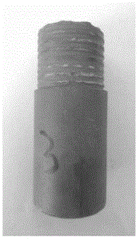
[0029] The second step: if image 3 As shown, the sintered silicon nitride ceramic workpiece 32 processed in the fir...

Embodiment 2

[0033] In this embodiment, through the cemented carbide turning tool clamped on the lathe tool holder, the axial low-speed feed completes the machining of the cylindrical silicon nitride ceramic outer circle, which includes the following steps:

[0034] The first step: groove the surface of the ceramic workpiece. like figure 1 As shown, the ceramic workpiece is clamped on the CNC grinding machine chuck 11, and the motor spindle 12 drives a small grinding wheel 13 with an outer diameter of 20mm to process a groove on the outer surface of the engineering ceramic 14 at a speed of 5000r / min (such as figure 2 ), the raised parts retained after processing form symmetrical edge bands 21 and sharp corner bands 22 at the bottom of the groove. The parameters of the groove are that the groove width 24 is 1 mm, the groove depth 25 is 0.5 mm, and the surface width 23 of the raised part is 1 mm.

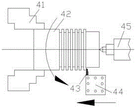
[0035] The second step: if Figure 4 As shown, the silicon nitride ceramics 42 are clamped...


PUM

PropertyMeasurementUnit
Groove depthaaaaaaaaaa

Abstract

The invention discloses a method for machining outer circles by the aid of edge cracking and horn effects, and belongs to the field of technologies for machining hard and brittle materials. The method includes machining spiral grooves or annular grooves on the surface of an outer circle of cylindrical engineering ceramics on a grinding machine by the aid of a diamond grinding wheel disc; clamping the ceramics on a lathe by the aid of a chuck and an apex, and axially feeding the engineering ceramics at a low speed to complete squeezing and machining on the surface of the outer circle of the engineering ceramics by the aid of a lathe tool clamped on a tool rest or a ceramic or hard alloy cylindrical squeezing tool which is turned by the aid of a high-speed motor; repeating the procedure, and feeding the tool repeatedly until the diameter of an axial section of the engineering ceramics meets dimensional requirements; buffing the surface of the outer circle of the engineering ceramics by the aid of a diamond grinding wheel so that quality requirements on the surface of the engineering ceramics can be met. The method has the advantages that consumed power for removing materials in a workpiece rough machining stage is low while the outer circle of the ceramics can be machined, loss of tools is low, and accordingly the machining cost can be reduced.

Description

technical field [0001] The invention belongs to the technical field of processing hard and brittle materials, and in particular relates to a novel processing method for engineering ceramic materials. Background technique [0002] Engineering ceramic materials are increasingly widely used in machinery, electronics, aerospace, energy, military and other fields because of their excellent properties such as high strength, high hardness, high temperature resistance, wear resistance, and corrosion resistance. Application and development of ceramic materials. [0003] Ordinary diamond grinding wheel grinding is the most commonly used processing method for engineering ceramics. Due to the rapid wear of the diamond grinding wheel, the processing cost is very high. In order to improve the grinding efficiency, scholars at home and abroad have successively proposed and developed ELID grinding, deep-cut slow-feed grinding, high-speed grinding, constant pressure grinding and high-speed d...

Claims


Application Information

Patent Timeline
IPC IPC(8): B24B19/02B28D1/16B24B5/04
CPCB24B1/00B24B19/02B28D1/00B28D1/16
Inventor 田欣利王龙王望龙吴志远唐修检王朋晓纪凯文
Owner 田欣利
Why Eureka
Try Eureka