
Ocean current generation flotation device

A technology of ocean current power generation and clamping device, which is applied in the direction of ocean energy power generation, engine components, machines/engines, etc. and other problems to achieve the effect of improving utilization

Active Publication Date: 2014-02-05
ZHEJIANG UNIV
View PDF6 Cites 2 Cited by
  • Summary
  • Abstract
  • Description
  • Claims
  • Application Information

AI Technical Summary

Problems solved by technology

Although the floating ocean current power generation device does not need to be installed and fixed on the seabed foundation, the ocean current power generation floating device will always float and move in a certain range of sea area with the flow of sea water, which affects the navigation and other marine operations in this sea area.
In the process of the ocean current power generation floating device floating with the sea water, it is difficult to maintain the horizontal working state of the ocean current power generation device, so that the upstream surface of the impeller cannot match the sea water flow at the best working angle, which reduces the energy utilization rate of the ocean current power

Method used


Image

  • Ocean current generation flotation device
  • Ocean current generation flotation device
  • Ocean current generation flotation device

Examples


Embodiment Construction

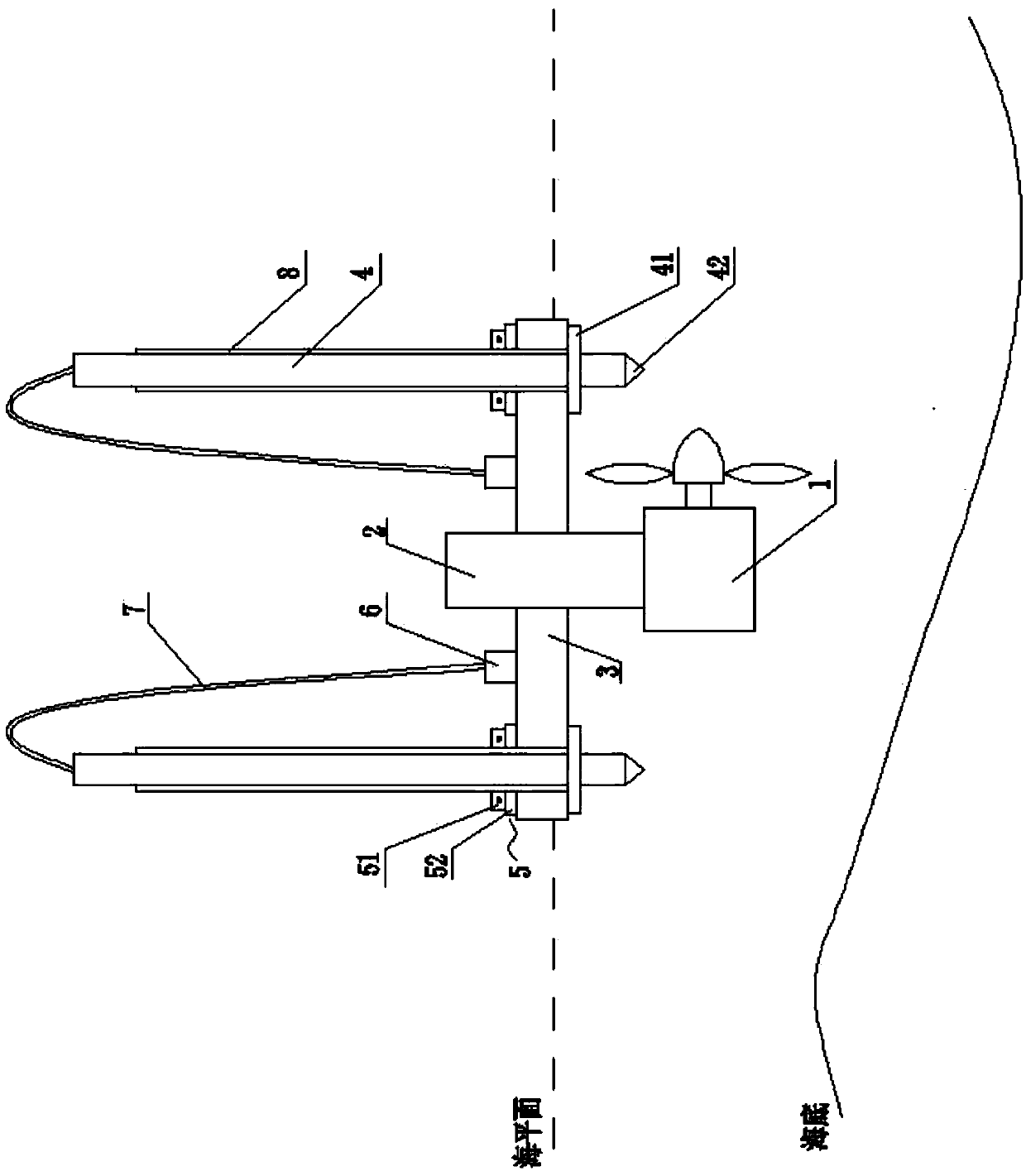
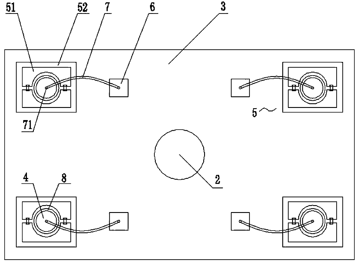
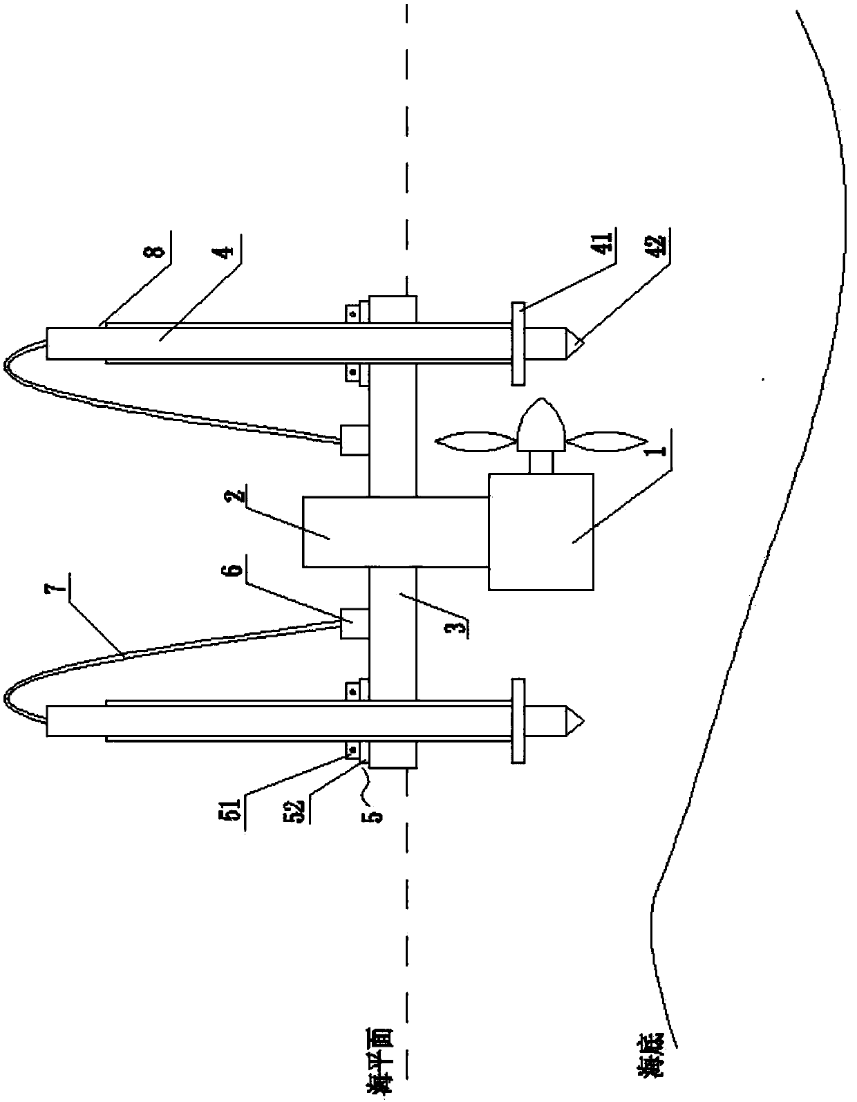
[0028] refer to figure 1 with figure 2 . An ocean current power generation floating device includes a steering column 2, a platform 3 and four sets of positioning devices, the platform 3 is a cuboid structure, and the four sets of positioning devices are symmetrically distributed at the four corners of the platform 3. The steering column 2 is located at the center of the platform 3, and the bottom end of the steering column 2 is fixed with an ocean current power generation device 1, and the steering column 2, together with the ocean current power generation device 1, can center line, and make a circular motion along the circumferential direction.

[0029] The positioning device includes a positioning column 4, a clamping device 5 and a pumping device 6, the clamping device 5 and the pumping device 6 are installed on the upper surface of the platform 3, and the positioning column 4 runs through the clamping device in turn. The tightening device 5 and the platform 3, the pos...


PUM


Abstract

The invention relates to an ocean current generation flotation device. The ocean current generation flotation device comprises a direction adjusting pillar, a platform and at least three sets of positioning devices; an ocean current generating set is arranged and fixed at the bottom end of the direction adjusting pillar; the direction adjusting pillar can take the circumferential rotating motion along the circumferential direction; the positioning device comprises a positioning pillar, a clamping device and a water pumping device; a hollow water storage cavity is formed inside each positioning pillar; the top of each positioning pillar is provided with a water injection hole; the water injection holes are connected with the corresponding water pumping devices arranged on the platform by pipelines; each positioning pillar sequentially penetrates through the corresponding clamping device and the platform; each positioning pillar can take the linear motion along the axial direction. The ocean current generation flotation device regulates the horizontal working state of the ocean current generating set by regulating displacement of each positioning pillar along the axial direction; the positioning pillars are chained with anchorage piers by anchor chains; the ocean current generating set can have a stable working environment. Meanwhile, by regulating the direction adjusting pillar to enable the incident flow face of an impeller of the ocean current generating set to be vertical to the flow direction of seawater, the energy utilization rate of ocean current energy is improved.

Description

technical field [0001] The invention belongs to the field of new energy utilization, and in particular relates to an ocean current power generation floating device. Background technique [0002] Ocean current power generation technology is a new energy utilization technology similar to wind power generation technology. It uses ocean current power generation devices to capture ocean current energy and convert it into electrical energy to provide users with power resources. When using the ocean current power generation device, it needs to be installed in the seawater environment, which involves the installation method of the ocean current power generation device in the ocean. The design of the installation method is related to the stability, reliability and safety of the operation of the entire ocean current power generation device sex. [0003] According to the different installation methods of the ocean current power generation device, the ocean current power generation dev...

Claims


Application Information

Patent Timeline
IPC IPC(8): F03B13/14
CPCY02E10/38Y02E10/30
Inventor 林勇刚谢卓君刘宏伟李伟石茂顺
Owner ZHEJIANG UNIV
Learn More