Mixing stirring device of mechanical stirring and source stirring of electromagnetic reverberation chamber and method

A technology of electromagnetic reverberation chamber and mechanical stirring, which is applied in the direction of measuring devices, parts of electrical measuring instruments, measuring electricity, etc., can solve the problems of limited statistical uniformity effect and unsuitable engineering realization, so as to improve the test efficiency and test The effect of repeatability, reduced manual intervention, and increased flexibility

Active Publication Date: 2014-02-05
陕西海泰电子有限责任公司
View PDF6 Cites 14 Cited by
  • Summary
  • Abstract
  • Description
  • Claims
  • Application Information

AI Technical Summary

Problems solved by technology

[0005] The above stirring methods each rely on a "single" variable change to change the electromagnetic field distribution in the reverberation chamber, so the statistical uniformity effect of the field that can be achieved is limited;
[0006] The literature "Analysis of Improving Field Uniformity in Reverberation Chamber Using Multi-antenna Source Stirring" studies the improvement of field uniformity in the test area of ​​the reverberation chamber brought about by the mixing and stirring method based on simulation, but its method of randomly setting multiple transmitting antennas is not suitable for Engineering realization; the document "Theoretical Analysis and Experimental Research of Electromagnetic Compatibility Reverberation Chamber" has proved through experiments that the mixing and stirring method can significantly improve the field uniformity of the test area in the reverberation chamber at low frequencies, but the mobile transmitting antenna used in it The method to multiple locations is also not suitable for engineering realization; therefore, exploring engineering feasible mixing methods has important application value

Method used


Image

  • Mixing stirring device of mechanical stirring and source stirring of electromagnetic reverberation chamber and method

Examples


Embodiment Construction

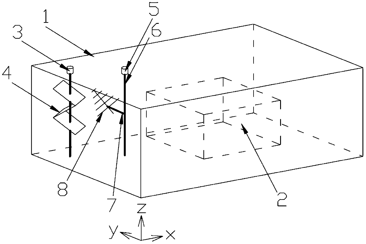
[0049] The present invention provides a mixing and stirring device for mechanical stirring and source stirring of an electromagnetic reverberation chamber, which includes an electromagnetic reverberation chamber 1, and also includes a mechanical stirring assembly and a source stirring assembly arranged on the side wall of the electromagnetic reverberation chamber 1; the mechanical stirring The assembly includes a first motor 3 and a mechanical stirrer 4 connected to the first motor 3; the source stirring assembly includes a second motor 5, a rotating shaft 6 connected to the second motor 5, and a transmitting antenna 8 arranged on the rotating shaft 6; The source stirring assembly also includes an extension arm 7 arranged on the rotating shaft 6 and a transmitting antenna 8 arranged on the extension arm 7; at least one extension arm 7; at least one mechanical stirring assembly; at least one source stirring assembly.

[0050] The invention provides a mixing and stirring method o...


PUM


Abstract

The invention provides a mixing stirring device of mechanical stirring and source stirring of an electromagnetic reverberation chamber. The mixing stirring device comprises the electromagnetic reverberation chamber and further comprises a mechanical stirring assembly and a source stirring assembly, wherein the mechanical stirring assembly and the source stirring assembly are arranged on the side wall of the electromagnetic reverberation chamber. The mechanical stirring assembly comprises a first motor and a mechanical stirrer connected with the first motor; the source stirring assembly comprises a second motor, a rotary shaft connected with the second motor and a transmitting antenna disposed on the rotary shaft. By means of combination of a mechanical stirring device, a source stirring device and a method, change of electromagnetic field distribution in the reverberation chamber depends on more variable changes which include changes of the length, the width and the height of an equivalent reverberation chamber and changes of the position of an excitation current source or/and orthogonal coordinate components of current density, and therefore more choices are provided for further improving field uniformity of a testing area in the reverberation chamber so that performance of the reverberation chamber is more likely to be improved.

Description

technical field [0001] The invention belongs to the technical field of electromagnetic compatibility testing, and relates to a mixing and stirring device and method for mechanical stirring and source stirring in an electromagnetic reverberation chamber. Background technique [0002] The existing electromagnetic reverberation chambers mainly include mechanical stirring reverberation chambers, source stirring reverberation chambers and other types. The stirring methods of various types of reverberation chambers are different, but the purpose is the same. They all change the electromagnetic field distribution in the reverberation chamber to achieve Statistical homogeneity of the electromagnetic field in the test area of ​​the reverberation chamber; [0003] The mechanical stirring reverberation chamber is equipped with a mechanical stirrer and a transmitting antenna. The transmitting antenna is fixed during operation, and the state of the stirrer changes many times, which is eq...

Claims


Application Information

Patent Timeline
Patent Type & Authority Applications(China)
IPC IPC(8): G01R1/02G01R31/00
Inventor 郭恩全肖宁汤兴刚许策
Owner 陕西海泰电子有限责任公司
Why Eureka
Try Eureka