Reflective imaging method and system for modulation-type diffuse reflection surface according to flight time principle

A time-of-flight and surface reflection technology, which is used in the re-radiation of electromagnetic waves, radio wave measurement systems, and the use of re-radiation. occluded objects, etc., to achieve the effect of extending the imaging range

Inactive Publication Date: 2014-02-05
ZHEJIANG UNIV
View PDF8 Cites 16 Cited by
  • Summary
  • Abstract
  • Description
  • Claims
  • Application Information

AI Technical Summary

Problems solved by technology

[0005] The general active imaging system can only detect objects that are directly irradiated by the detection light. If the target object is blocked by obstacles, it is difficult for the imaging system to detect the existence of the target object. Therefore, the traditional three-dimensional lidar cannot detect objects blocked by obstacles. objects, which limit the working range of 3D lidar in many applications

Method used


Image

  • Reflective imaging method and system for modulation-type diffuse reflection surface according to flight time principle
  • Reflective imaging method and system for modulation-type diffuse reflection surface according to flight time principle
  • Reflective imaging method and system for modulation-type diffuse reflection surface according to flight time principle

Examples


specific Embodiment

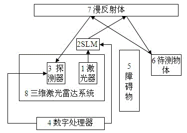
[0060] A three-dimensional laser radar system is 15 meters away from the diffuse reflector, and the object to be measured is 3 meters away from the diffuse reflector as the imaging implementation environment. The laser adopts the BLT-532-0501005 laser from Melis Griot Company of the United States, the spatial light modulator adopts Holoeye LC-R3000SLM, the detector adopts the PI MAX enhanced CCD camera of Princeton Instruments, the digital processor adopts a personal computer, the obstacle is a wall, diffuse reflection The body is the wall. The object to be tested is a tree obscured by a wall.

[0061] 1) The light pulses emitted by the BLT-532-0501005 laser pass through the spatial light modulator Holoeye LC-R3000SLM without phase modulation and reflect off the wall to illuminate the trees. After passing through the wall, they are received by the PI MAX enhanced CCD camera to obtain the phase without loading 3D image 0.

[0062] 2) The light pulses emitted by the BLT-532-05...


PUM


Abstract

The invention discloses a reflective imaging method and system for a modulation-type diffuse reflection surface according to the flight time principle. Laser emitted by a laser device is reflected to an object to be detected after passing through a spatial light modulator and the surface of a diffuse reflection body. After reflective light of the object to be detected is re-reflected through the surface of the diffuse reflection body, the reflective light is received by a detector controlled by a digital processor at different photonic flight times, and the object to be detected, which is sheltered by a barrier can be restored according to the elliptical distribution conditions of a contour map of an image. The digital processor is connected with the spatial light modulator, the laser device and the detector, and the laser device is connected with the spatial light modulator. The barrier is arranged between a three-dimensional laser radar system and the object to be detected. Output light, modulated through the spatial light modulator, of the laser device irradiates on the object to be detected by passing the diffuse reflection body, and the reflective light of the object to be detected is received by the detector by passing the diffuse reflection body. A non-direct-view object which can not be detected by an imaging system of a traditional optical system can be detected through the reflective imaging method and system, and therefore the imaging range of a three-dimensional laser radar is expanded.

Description

technical field [0001] The invention relates to a diffuse reflection surface reflection imaging method and system, in particular to a time-of-flight modulation diffuse reflection surface reflection imaging method and system. Background technique [0002] Lidar is the product of the combination of laser technology and radar technology. It is composed of transmitters, antennas, receivers, tracking frames and information processing. It can accurately measure the target position (distance and angle), motion status (speed, vibration and Attitude) and shape, detect, recognize, distinguish and track targets. In 1967, the spaceborne lidar developed by the American International Telephone and Telegraph Company was used for the rendezvous and docking of space flight flags, which opened a precedent for the application of lidar. After decades of development, the development process of laser radar from simple to complex, from low-level to high-level, the types are increasing, the functi...

Claims


Application Information

Patent Timeline
Patent Type & Authority Applications(China)
IPC IPC(8): G01S17/89
CPCG01S17/36G01S17/89
Inventor 严惠民张秀达吴雨霖崔永胜尹煜
Owner ZHEJIANG UNIV
Why Eureka
Try Eureka