
Integrated device for realizing light polarization beam splitting and rotation

An integrated device and optical polarization technology, applied in the field of integrated photonics, can solve the problems of reducing stability, increasing the cost of polarization diversity solutions, and complex processing of integrated polarization rotators, and achieves the effect of wide working wavelength range and simple structure

Inactive Publication Date: 2014-02-05
NINGBO YINUO ELECTRONICS TECH
View PDF3 Cites 4 Cited by
  • Summary
  • Abstract
  • Description
  • Claims
  • Application Information

AI Technical Summary

Problems solved by technology

[0004] In this traditional polarization diversity scheme, the polarization beam splitter and the polarization rotator are two independent components, and the processing of the traditional integrated polarization rotator is relatively complicated, requiring multiple coating, photolithography and etching processes
These have greatly increased the cost of the implementation of the polarization diversity scheme and reduced its stability

Method used


Image

  • Integrated device for realizing light polarization beam splitting and rotation
  • Integrated device for realizing light polarization beam splitting and rotation
  • Integrated device for realizing light polarization beam splitting and rotation

Examples


Embodiment 1

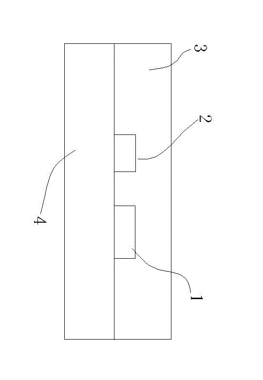
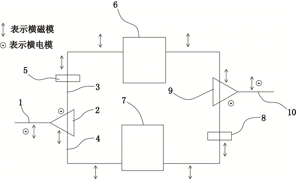
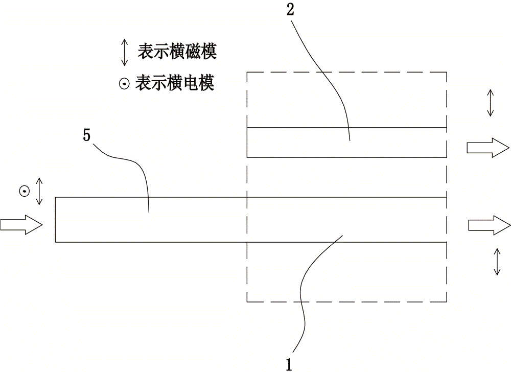
[0020] An integrated device for realizing optical polarization beam splitting and rotation, including two first straight waveguides 1 and second straight waveguides 2 arranged in parallel, the first straight waveguide 1 and the second straight waveguide 2 are made of high refractive index materials, generally should be greater than or equal to 2.8. In this embodiment, silicon is used. An upper cladding layer 3 is arranged above the first straight waveguide 1 and the second straight waveguide 2, and a lower cladding layer 4 is arranged below to form a coupling region, wherein, The refractive index of the upper cladding layer 3 and the lower cladding layer 4 is lower than the refractive index of the first straight waveguide 1 and the second straight waveguide 2, and the refractive index of the upper cladding layer 3 is greater than or smaller than that of the lower cladding layer The refractive index of layer 4, generally the refractive index of the upper cladding layer 3 and the...

Embodiment 2

[0024] An integrated device for realizing optical polarization beam splitting and rotation, including two first straight waveguides 1 and second straight waveguides 2 arranged in parallel, the first straight waveguide 1 and the second straight waveguide 2 are made of high refractive index materials, generally should be greater than or equal to 2.8. In this embodiment, silicon is used. An upper cladding layer 3 is arranged above the first straight waveguide 1 and the second straight waveguide 2, and a lower cladding layer 4 is arranged below to form a coupling region, wherein, The refractive index of the upper cladding layer 3 and the lower cladding layer 4 is lower than the refractive index of the first straight waveguide 1 and the second straight waveguide 2, and the refractive index of the upper cladding layer 3 is greater than or smaller than that of the lower cladding layer The refractive index of layer 4, generally the refractive index of the upper cladding layer 3 and the...


PUM


Abstract

The invention discloses an integrated device for realizing light polarization beam splitting and rotation. The integrated device comprises a first straight waveguide and a second straight waveguide which are arranged in parallel. An upper cladding layer is arranged above the first straight waveguide and the second straight waveguide, and a lower cladding layer is arranged under the first straight waveguide and the second straight waveguide so as to form a coupling region. The refractive index of the upper cladding layer and the refractive index of the lower cladding layer are less than the refractive index of the first straight waveguide and the refractive index of the second straight waveguide, and the refractive index of the upper cladding layer is greater than or less than the refractive index of the lower cladding layer. Compared with the prior art, waveguides which are asymmetric in the vertical direction are formed according to the structure of the invention, and the coupling region structure can be used to support strong cross coupling effect. Through the cross coupling effect with the waveguides which are asymmetric in the vertical direction, through the two waveguide which are coupled in parallel, and the polarization beam splitting and polarization rotation effects can be realized through the directional coupling method.

Description

technical field [0001] The invention relates to the field of integrated photons, in particular to an integrated device for realizing light polarization beam splitting and polarization rotation based on a high refractive index difference waveguide. The device can be used in polarization diversity integrated optical circuit. Background technique [0002] After years of development, the size of integrated photonic devices has been gradually reduced. The integration level of integrated photonic chips is developing at a speed exceeding Moore's law of integrated electronics. In recent years, high refractive index difference nanowire waveguides and their devices represented by silicon-on-insulator (SOI) materials have attracted widespread attention. The material has many advantages. First, its device processing method is compatible with the widely used integrated circuit CMOS process. Secondly, due to the use of a high refractive index difference structure, the size of the SOI w...

Claims


Application Information

Patent Timeline
Patent Type & Authority Applications(China)
IPC IPC(8): G02B6/126G02B6/24
Inventor 郑志强
Owner NINGBO YINUO ELECTRONICS TECH
Learn More