PFC control method and control device

A technology of control device and subtraction operation, applied in the direction of output power conversion device, high-efficiency power electronic conversion, electrical components, etc., can solve the problem that the distorted current has no improvement effect, cannot improve the working current waveform of the PFC circuit, and the work of the power unit Problems such as the deterioration of the current waveform can achieve the effect of improving the PF value

Active Publication Date: 2014-02-05
MORNSUN GUANGZHOU SCI & TECH
View PDF3 Cites 5 Cited by
  • Summary
  • Abstract
  • Description
  • Claims
  • Application Information

AI Technical Summary

Problems solved by technology

[0015] (1) It is impossible to improve the working current waveform of the power consumption unit where the existing PFC circuit is located;
[0016] (2) There are other distorted loads in the power unit, and the working current waveform of the power unit further deteriorates
[0017] That is, the existing PFC circuit does not improve the surrounding distorted current in the power system

Method used


Image

  • PFC control method and control device
  • PFC control method and control device
  • PFC control method and control device

Examples


no. 1 example

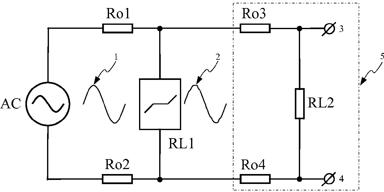
[0043] Figure 5 The block diagram of the first embodiment is shown, which shows the current feedback PFC device using the method of the present invention, including: a rectifier bridge composed of four rectifier diodes Da, Db, Dc, Dd, and an inductor L1 and power The classic Boost PFC circuit topology composed of tube Q1, diode D1, and capacitor C1; and the feedback signal attenuation unit 1 / H, comparator unit, and current peak detection circuit IA form the current feedback part; the comparator unit also includes a built-in current error amplifier, Pulse width modulators and drivers, etc., belong to the prior art, Figure 5 Not shown in the figure, its load is a main power MOS transistor Q1 of a classic PFC circuit topology; the attenuation unit 1 / H also includes a built-in reference voltage and an error amplifier, which also belongs to the prior art. Figure 5 Not shown in , the function of the attenuation unit is to divide the voltage, and it is also used as a voltage divi...

no. 2 example

[0058] Image 6 Shown is the functional block diagram of the second embodiment, showing the PFC device applying the method of the present invention, including: a rectifier bridge composed of four rectifier diodes Da, Db, Dc, Dd, and an inductor L1 and a power transistor Q1, diode The classic Boost PFC circuit topology composed of D1 and capacitor C1; and the current feedback part composed of feedback signal attenuation unit 1 / H, comparator unit, and current peak detection circuit IA; the comparator unit also includes a built-in current error amplifier, pulse width modulation Drives and drivers, etc., belong to the prior art, Image 6Not shown in the figure, its load is a main power MOS transistor Q1 of a classic PFC circuit topology; the attenuation unit 1 / H also includes a built-in reference voltage and an error amplifier, which also belongs to the prior art. Image 6 Not shown in , the function of the attenuation unit is to divide the voltage, and it is also used as a volta...


PUM


Abstract

The invention discloses a PFC control method and device. Electric supply alternating voltages and an undistorted standard same-phase sine fundamental wave are compared, finally distorted signals with the proper number of fundamental waves are obtained, the distorted signals reflect the distortion situation of electric supply, the signals are used for controlling working currents of a PFC device, so that the working currents of the PFC device are in the half-wave form of electric supply, when heavy load happens instantly, the device consumes low working currents or does not consume working currents, when relatively-light load happens instantly, high working currents are consumed, so that electric supply voltage wave form distortion is reduced, therefore, the whole PF value of an electric unit is improved, other distortion load exists in the electric unit, the PFC device can still work well, and the whole PF value of the electric unit is improved.

Description

technical field [0001] The present invention relates to a PFC control method for a power factor correction (PFC) device, and the present invention also relates to a control device using the above method. Background technique [0002] Both industrial and civil use often need to change the AC voltage of various power grids into DC, or even isolated DC. With the further requirements of the national standard on the power factor (PF) of electrical appliances, at present, switching power supplies with a power consumption of more than 75W are required. There is a power factor requirement, that is, the operating current waveform of the circuit is required to be basically the same as the voltage waveform. [0003] At present, there is a power factor correction circuit to solve this problem. The power factor correction circuit is referred to as a PFC circuit for short, which is the abbreviation of Power Factor Correction. [0004] Note: The 75W data comes from the Chinese national st...

Claims


Application Information

Patent Timeline
Patent Type & Authority Applications(China)
IPC IPC(8): H02M1/42
CPCY02B70/126Y02B70/10
Inventor 王保均
Owner MORNSUN GUANGZHOU SCI & TECH
Why Eureka
Try Eureka