

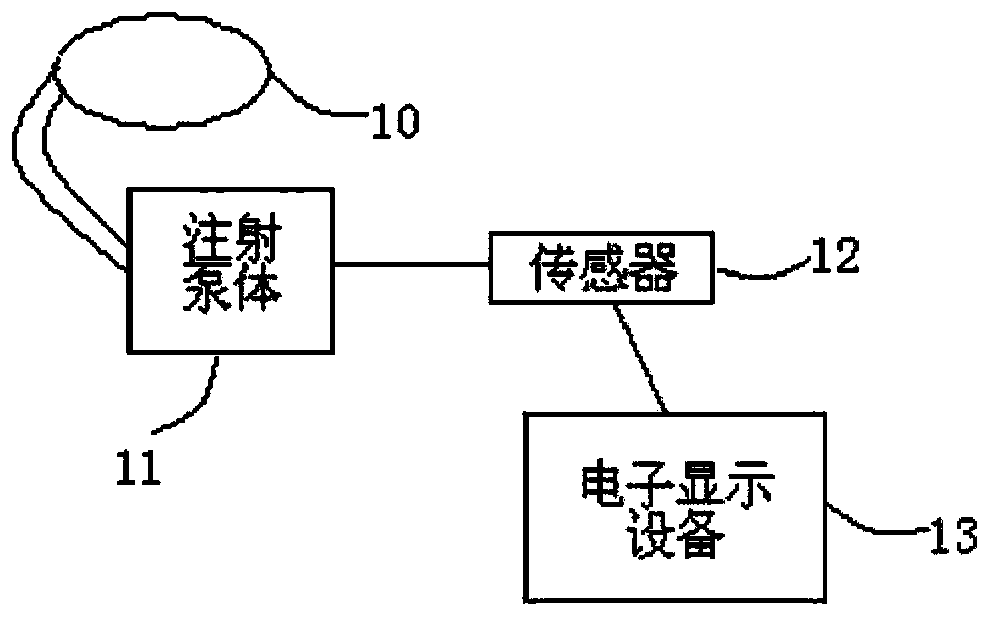
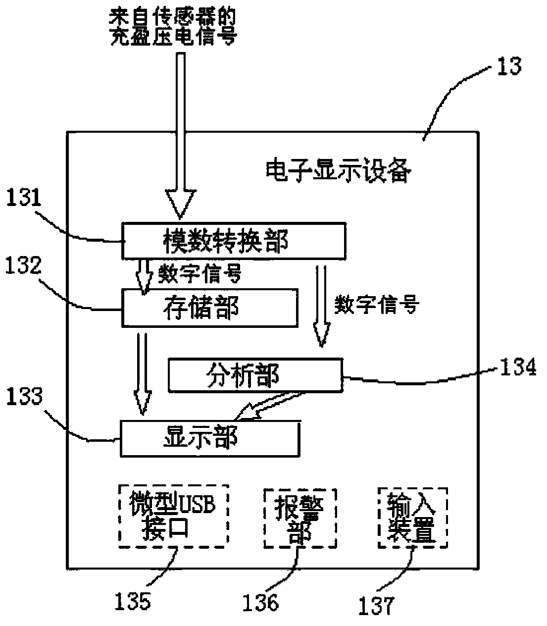
Balloon filling device
A balloon filling technology, applied in dilators, catheters, surgery, etc., can solve the problems of inability to monitor the peak filling pressure, low compliance, and insufficient functions, and achieve improved readability, good accuracy, and easy operation Effect
- Summary
- Abstract
- Description
- Claims
- Application Information
AI Technical Summary
Problems solved by technology
Method used
Image

Examples
Embodiment Construction
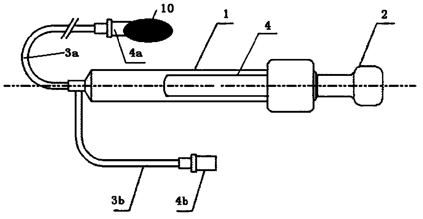
[0032] In order to further understand the present invention, preferred solutions of the present invention will be described below in conjunction with examples. These descriptions only illustrate the features and advantages of the present invention, but do not limit the protection scope of the present invention. Hereinafter, the terms "fluid connection" and "fluid communication" are used in many places, and the two terms have the same meaning. In this disclosure, the path length of "fluid connection" or "fluid communication" is relatively short, there is basically no potential energy difference, and the fluid on the path The mass is sufficiently small so that the kinetic energy is also small, so that according to fluid dynamics, it can be understood that the pressure at each point on the "fluid connection" or "fluid communication" path (hereinafter referred to as "filling pressure") is equal. In addition, the applicant has tested the fluid communication path between the syringe...
PUM
 Abstract
Description
Claims
Application Information