Method of beam cap connection for lengthening wind turbine generator blades

A technology for wind turbines and connection methods, which is applied to wind turbine components, wind engines, and wind power generation, and can solve problems such as reducing the clearance between blades and towers, stress concentration at the bonding interface, and increasing the risk of blades hitting the tower. Achieve the effects of avoiding the risk of beating the tower, improving the bonding interface, and optimizing the stiffness distribution

Active Publication Date: 2014-02-12
BEIJING KHANWIND TECH
View PDF6 Cites 9 Cited by
  • Summary
  • Abstract
  • Description
  • Claims
  • Application Information

AI Technical Summary

Problems solved by technology

However, for the blade lengthened and transformed by this method, the existing blade spar cap and the blade tip extension spar cap are all UD glass fiber laminates, the thickness and width of the laminate have not changed, and the two spar caps are only bonded by structural adhesives. , there are two problems in this modified structure: First, the two sections of beam caps are bonded by structural glue, which means that the stress transfer between the two sections of beam caps UD glass fibers is completed through structural glue, resulting in discontinuous structure , and under the influence of negative factors such as uneven thickness of structural glue or local lack of glue, local bubbles, etc., it is easy to cause stress concentration at the bonding interface, and it is easy to cause fatigue damage under the action of alternating loads, and eventually cause the blade spar cap Second, the distribution of the stiffness of the blade itself is the same as that of the existing blade without modification. When the length of the blade increases, the deformation of the lengthened blade will increase, which reduces the clearance value between the blade and the tower, and increases the blade's impact on the tower. risk

Method used


Image

  • Method of beam cap connection for lengthening wind turbine generator blades
  • Method of beam cap connection for lengthening wind turbine generator blades
  • Method of beam cap connection for lengthening wind turbine generator blades

Examples


Embodiment 1

[0045] Step 1: Prefabrication of the reserved area of ​​the existing blade spar cap

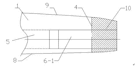
[0046] 1a. If figure 1 As shown, the identification of the cutting and grinding area of ​​the existing blade, referring to the structure and process requirements of the lengthened wind power blade, identifies the lengthened connecting surface 4, the reserved area of ​​the existing blade spar cap 6-1, and the grinding and bonding area of ​​the blade tip shell 10;

[0047] 1b. For the grinding of the reserved area 6-1 of the existing blade spar cap, the grinding process shall be carried out with reference to the marking line of 1a. In the staggered transition zone of the blade spar cap 5, the single-layer staggered distance in the transition zone is greater than 100mm, the grinding width is the same as the width of the existing blade spar cap glass fiber layup, and the grinding thickness is the same as the existing spar cap glass fiber layup at the 4 extended joints thickness;

[0048] 1...

Embodiment 2

[0065] Step 1: Prefabrication of the reserved area of ​​the existing blade spar cap

[0066] 1a. Marking of the cutting and grinding area of ​​the existing blades. Referring to the structure and process requirements of the lengthened wind power blades, mark the lengthened connecting surface 4, the reserved area of ​​the beam cap of the existing blade 6-1, and the grinding and bonding area of ​​the blade tip shell 10 ;

[0067] 1b. For the grinding of the reserved area 6-1 of the existing blade spar cap, the grinding process shall be carried out with reference to the marking line of 1a. In the staggered transition zone of the blade spar cap 5, the single-layer staggered distance in the transition zone is greater than 100mm, the grinding width is the same as the width of the existing blade spar cap glass fiber layup, and the grinding thickness is the same as the existing spar cap glass fiber layup at the 4 extended joints thickness;

[0068] 1c. Grinding of the bonding area 1...


PUM


Abstract

The invention relates to the method of beam cap connection for lengthening wind turbine generator blades. The method is particularly adopted for connecting beam caps of the blades in the lengthening and improving process of existing wind turbine generator blades. Each reinforced beam cap is manufactured in a beam cap reserved zone between one existing beam cap of one blade and the corresponding beam cap of one blade tip lengthening section, so that the problem of connection of every two existing beam caps is solved. The blades which are lengthened and improved through the method for connecting the beam caps of the wind turbine generator blades are safe and reliable in structure.

Description

technical field [0001] The invention relates to a manufacturing technology of wind power generator blades, in particular to a spar cap connection method for lengthening existing wind power generator blades. Background technique [0002] At least some known wind power generators are composed of wind rotor blades, drive shafts, generators, towers and related control systems. The wind rotor blades have specific aerodynamic airfoils, which form rotation at a certain speed after absorbing wind energy energy, and then the rotational energy is converted into electrical energy by a generator. [0003] The selection of wind turbines is crucial to the development of a wind farm project, and it is directly related to the economic benefits of the wind farm project. As a general principle, for unit selection, try to select units whose design level is equal to that of the wind farm. Of course, units with a higher design level can be used in lower-level wind farms. From a technical poin...

Claims


Application Information

Patent Timeline
Patent Type & Authority Applications(China)
IPC IPC(8): F03D11/00
CPCY02E10/722Y02E10/72Y02P70/50
Inventor 霍唐军张旺杜瑛卓刘军华鲍春宇
Owner BEIJING KHANWIND TECH
Why Eureka
Try Eureka