

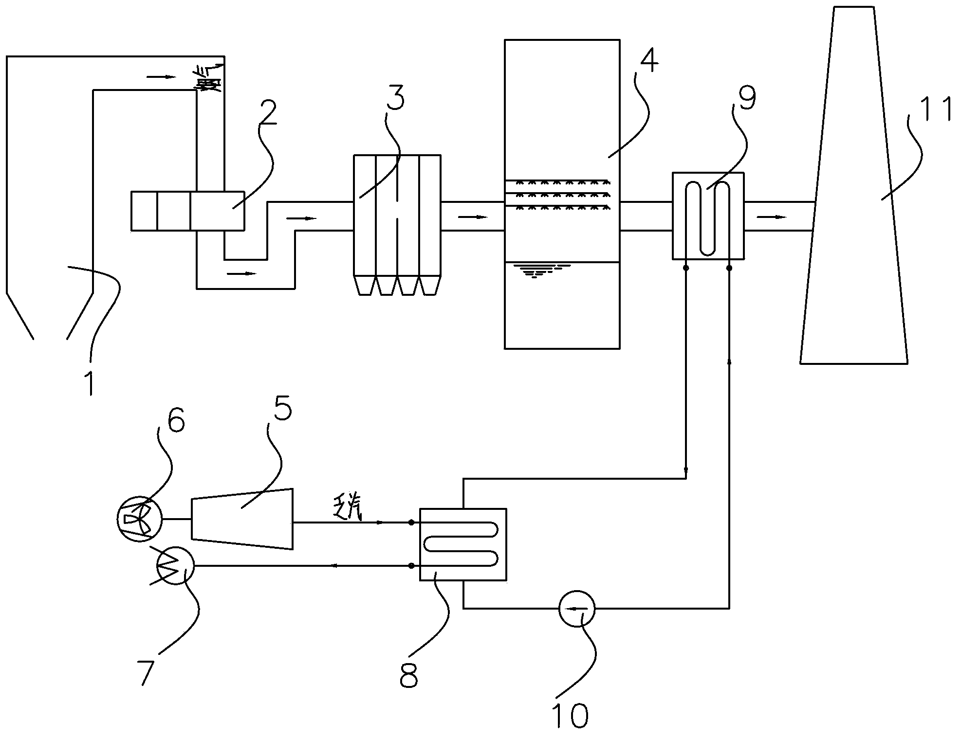
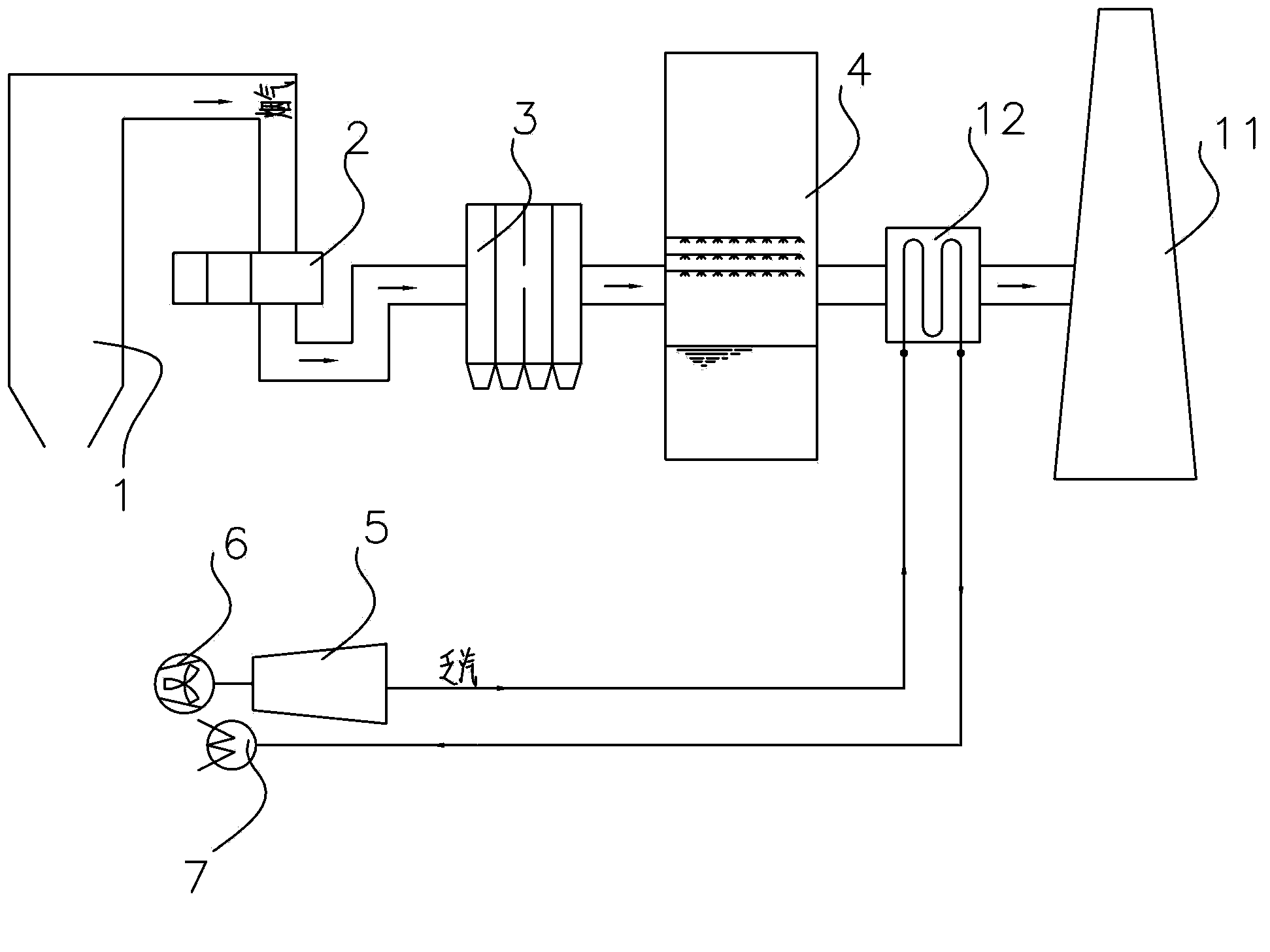
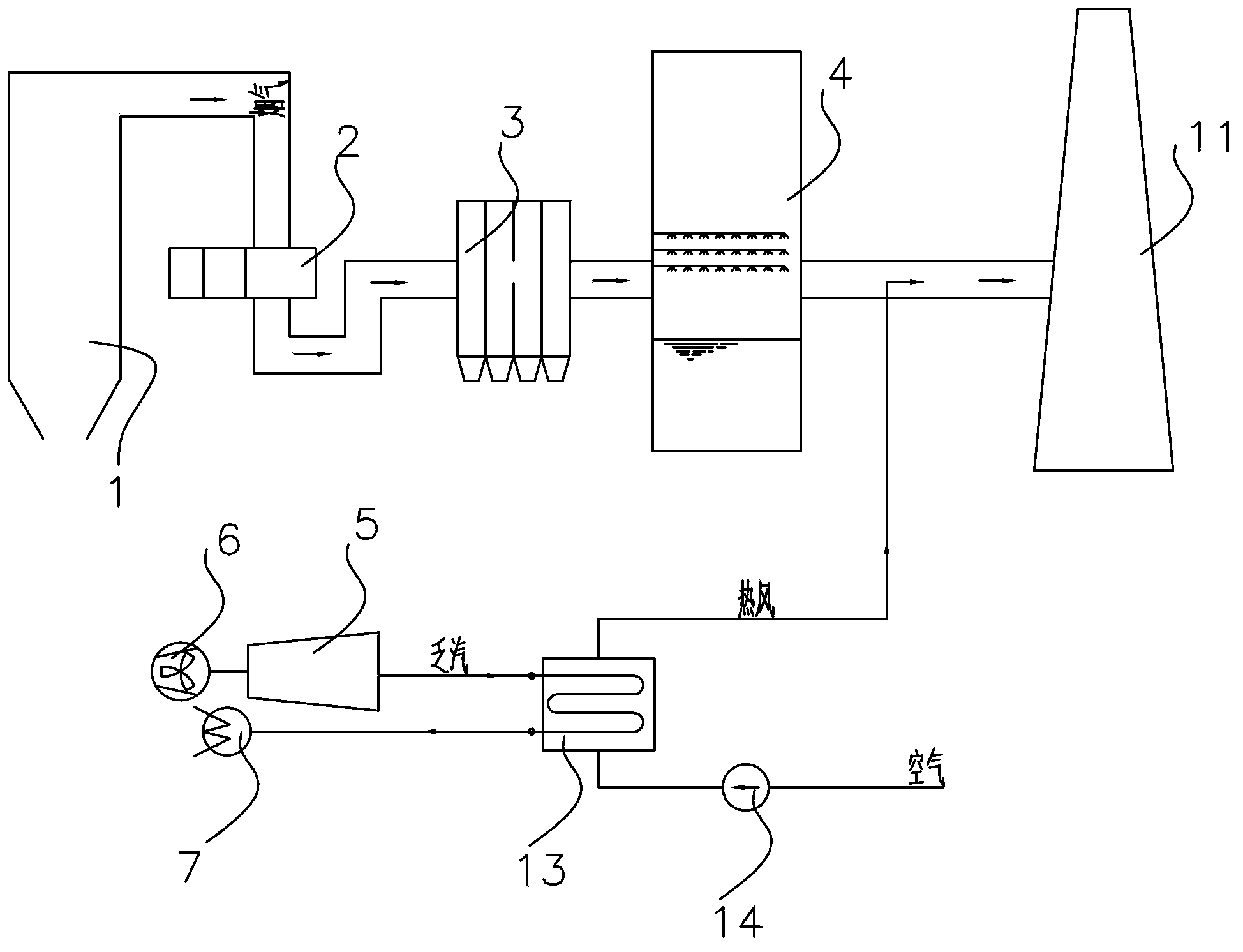
Method for improving temperature of smoke discharged by chimney of thermal power plant, smoke heating system and thermal power generation unit
A flue gas heating and chimney exhausting technology, applied in the field of flue gas heating systems, can solve the problems of expensive and corrosion-resistant chimneys, affecting the environment of the power plant area, and being unable to be used by the power plant, so as to eliminate adverse effects, be conducive to environmental protection, The effect of increasing the lift height
- Summary
- Abstract
- Description
- Claims
- Application Information
AI Technical Summary
Problems solved by technology
Method used
Image

Examples
Embodiment Construction
[0031] Preferred embodiments of the present invention will be described in detail below with reference to the accompanying drawings, so as to better understand the purpose, features and advantages of the present invention. It should be understood that the embodiments shown in the drawings are not intended to limit the scope of the present invention, but only to illustrate the essence of the technical solutions of the present invention. The same or similar parts in the figures are denoted by the same reference numerals.
[0032] Hereinafter, main technical terms of the present invention will be described.
[0033] Herein, the boiler mainly includes a boiler device. The boiler device is not specifically limited, as long as it does not limit the purpose of the present invention, it is known to those skilled in the art. It can use π-type boilers (or Pai-type boilers), tower boilers, inverted U-shaped boilers, etc., coal-fired boilers, oil-fired boilers, etc., natural circulation...
PUM
 Abstract
Description
Claims
Application Information